
Plug structure

a plug and structure technology, applied in the direction of packaging, transportation and packaging, liquid transfer devices, etc., can solve the problems of rate measurement and quality control, easy pooling of liquid,

Active Publication Date: 2009-07-30
SURPASS IND
View PDF6 Cites 26 Cited by
  • Summary
  • Abstract
  • Description
  • Claims
  • Application Information

AI Technical Summary

Benefits of technology

[0018]According to the invention described above, a plug structure, which is used in a container that is filled with a fluid such as a chemical product and which is provided with a siphon hose for removing the fluid to the outside of the container, can be installed in a container in which the thread of the container inlet for installing the cap is an external thread. Furthermore, the plug structure is one in which, during fluid circulation, when a fluid such as a chemical product is circulated, because it is possible to cause the fluid to fall to the fluid surface along the outer wall of the siphon hose, bubbles are not produced on the fluid surface inside the container.

Problems solved by technology

Note that in this conventional technology, because gas holes are provided in the side surface of a center plug, another problem that has been pointed out is that fluid pooling occurs easily.
However, this is not preferable in terms of accurate flow rate measurement and quality control and the like because such bubbles indicate that gas has become trapped in the fluid, such as a chemical product.

Method used


Image

  • Plug structure
  • Plug structure
  • Plug structure

Examples


Embodiment Construction

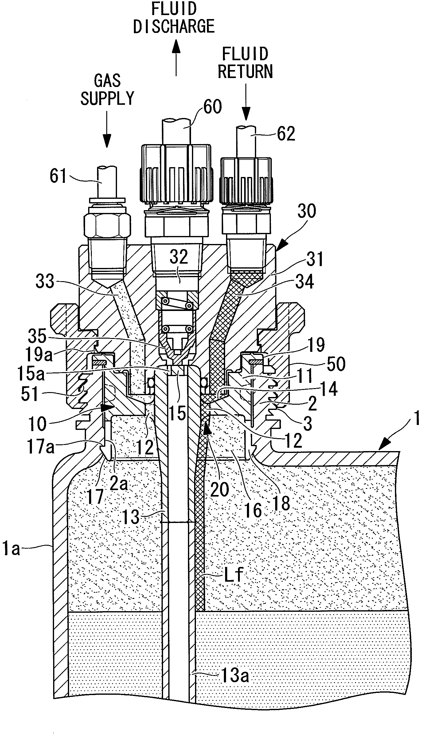
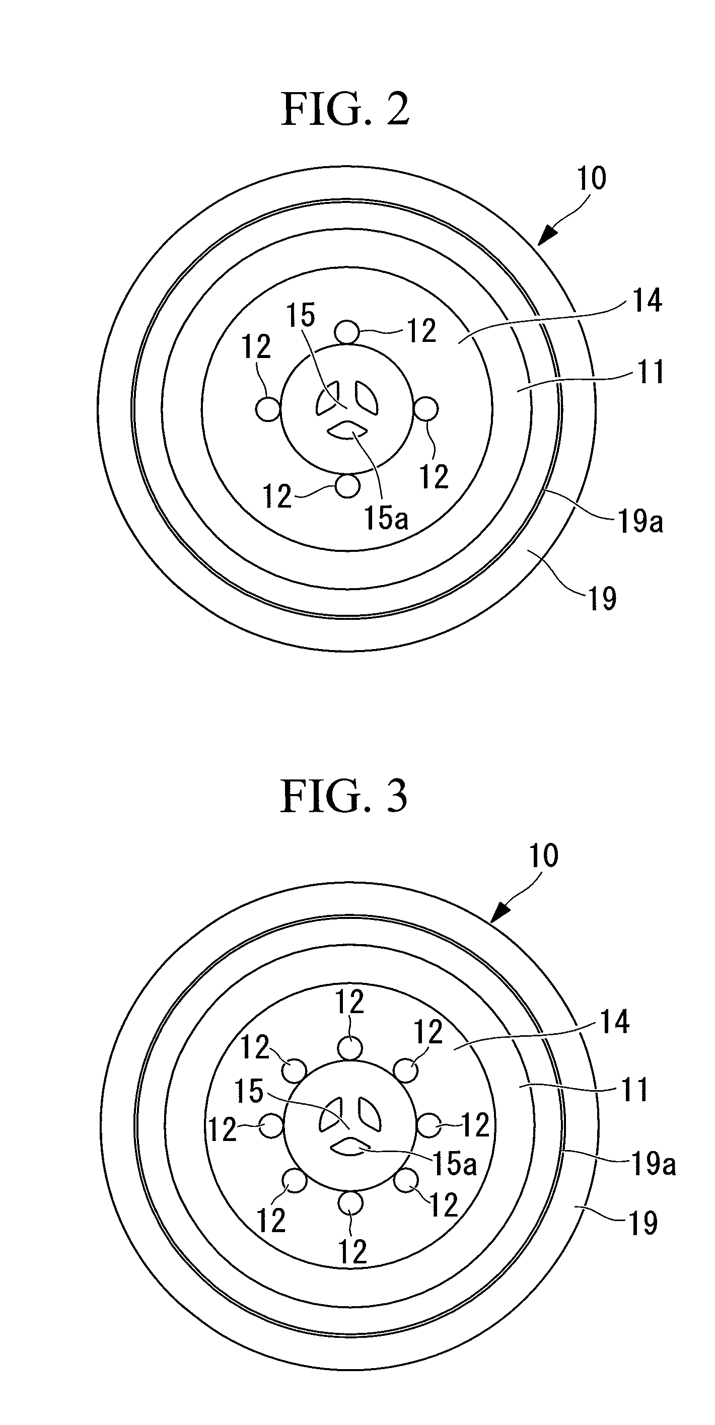
[0030]Below, an embodiment of the plug structure according to the present invention will be explained with reference to FIG. 1 and FIG. 2.

[0031]In FIG. 1 and FIG. 2, reference numeral 1 denotes a container, reference numeral 10 denotes a plug, and reference numeral 30 denotes a socket. In order to remove a fluid that is stored in the inside of the container 1, the plug 10 of the present invention uses a siphon hose method in which a gas, such as air, is introduced to the inside of the container 1, and the fluid is fed to the outside of the container 1 due to the gas pressure generated thereby. In addition, in the case in which the socket 30 is provided with a fluid return path 34, which will be described below, this plug 10 is used to circulate the fluid that is inside the container 1 in addition to being used to remove the fluid that is inside the container 1.

[0032]The container 1 that is filled with a chemical fluid (fluid), such as a high-purity chemical product for semiconductor...


PUM


Abstract

A plug structure is provided that can be installed on a container in which the thread of a container inlet for installing a cap is an outer thread, and furthermore, bubbles are not produced at the fluid surface inside the container even during fluid circulation. In a plug structure that is used in a container in which the thread of the container inlet for attaching the cap is an external thread, that is installed on the container inlet, that is capable of removing a fluid inside the container by using the siphon hose method, and that is capable of circulating the fluid that is inside the container, a fluid circulation path is provided that causes a fluid that is returning into the container during fluid circulation to fall along an external wall of a siphon hose during fluid removal.

Description

CROSS REFERENCE TO RELATED APPLICATIONS[0001]This application claims priority to Japanese Patent Application No. 2008 016234, filed on Jan. 28, 2008, the contents of which are incorporated herein by reference.FIELD OF THE INVENTION[0002]The present invention relates to a plug structure that is attached to an opening of a container in which fluids such as high-purity chemical products for semiconductors and general-use chemical products and the like are stored, and in particular, relates to a plug structure that can circulate the fluid that is in the container.BACKGROUND OF THE INVENTION[0003]Generally, fluids such as high-purity chemical products for semiconductors and general-use chemical products and the like are filled into containers such as glass bottles and polyethylene tanks at a production facility, and they are then shipped with a lid attached to the opening for filling and discharging that is formed in this fluid tank. One known method for removing the fluid that has been ...

Claims


Application Information

Patent Timeline
IPC IPC(8): B65D51/16B67D7/78B67D7/02
CPCB65D51/1683B67D7/0288B67D7/0294Y10T137/85954Y10T137/314B65D41/62B65D51/18B61D5/08
Inventor TAKANOHASHI, TOSHIYUKI
Owner SURPASS IND
Features
  • Generate Ideas
  • Intellectual Property
  • Life Sciences
  • Materials
  • Tech Scout
  • Unparalleled Data Quality
  • Higher Quality Content
  • 60% Fewer Hallucinations
Learn More