Hinge mounted fuel housing seal

a fuel housing and sealing technology, applied in the direction of roofs, transportation and packaging, propulsion parts, etc., can solve the problems of ineffective sealing attempts of door panels against the housing structure, inability to open the access door, and contamination that enters the housing area, so as to prevent contamination. the effect of intrusion

Active Publication Date: 2009-07-30
ILLINOIS TOOL WORKS INC
View PDF23 Cites 34 Cited by
  • Summary
  • Abstract
  • Description
  • Claims
  • Application Information

AI Technical Summary

Benefits of technology

[0007]The present invention provides a fuel system housing to contain the filler tube inlet, with a hinged door on the housing having a seal on the inner hinge structure to prevent intrusion of contaminants into the housing interior.
[0012]Another advantage of another form of the invention is providing a fuel system inlet housing for vehicles that provides an effective barrier against contaminants including dirt, rain and snow that is easy to operate.

Problems solved by technology

As a result, debris such as water, dirt, ice and the like may find its way into the fuel housing boxed in area around the filler tube inlet.
A disadvantage of not having a cap is that contaminants that enter the housing area can accumulate on the end of the filler tube inlet, specifically on the outer surface of the sliding structures that are moved out of the way when a refueling nozzle is inserted.
Attempts to seal the door panel against the housing structure have not been effective in that the sealing relationship is difficult to establish and maintain and can make the access door difficult to open.

Method used


Image

  • Hinge mounted fuel housing seal
  • Hinge mounted fuel housing seal
  • Hinge mounted fuel housing seal

Examples


Embodiment Construction

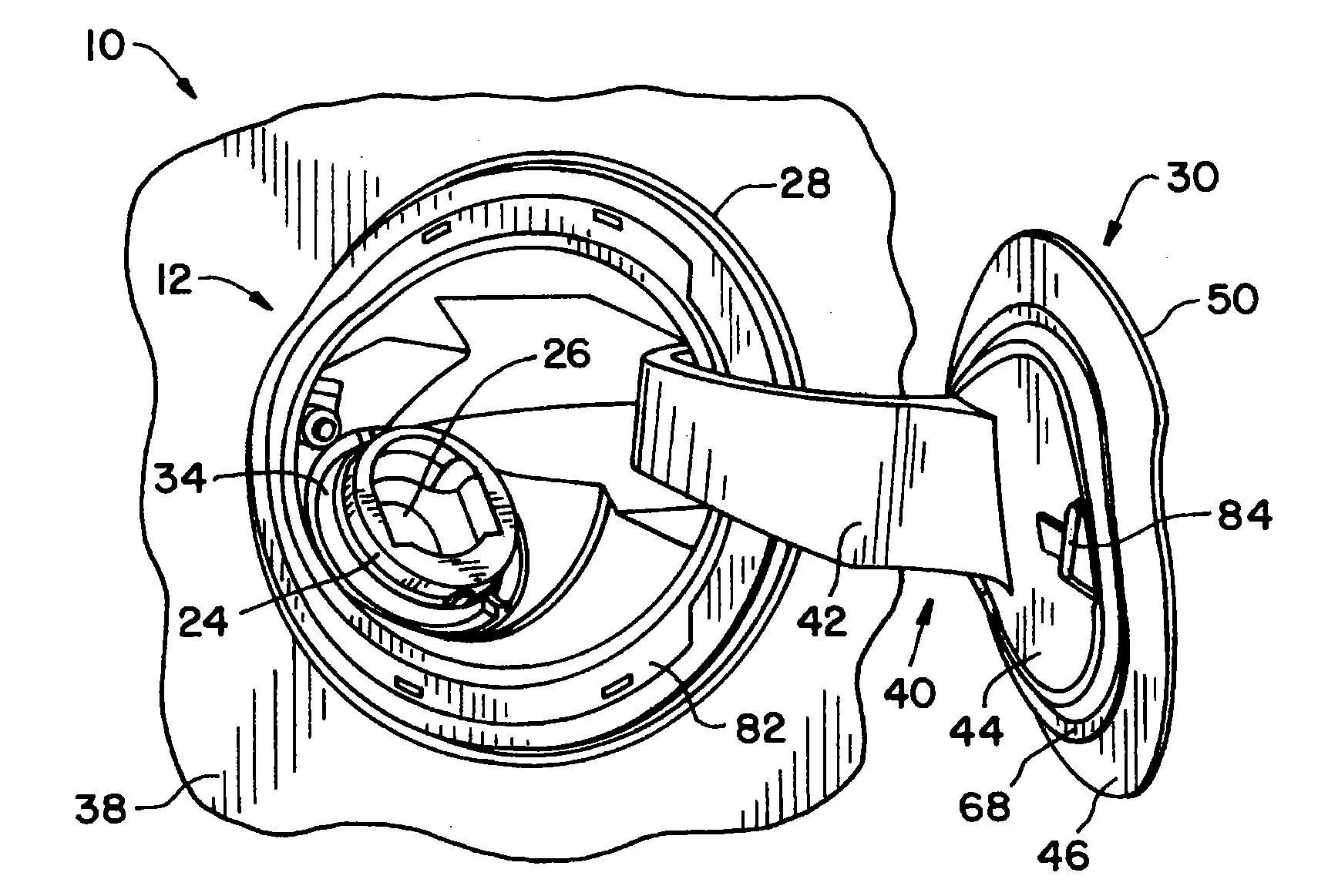
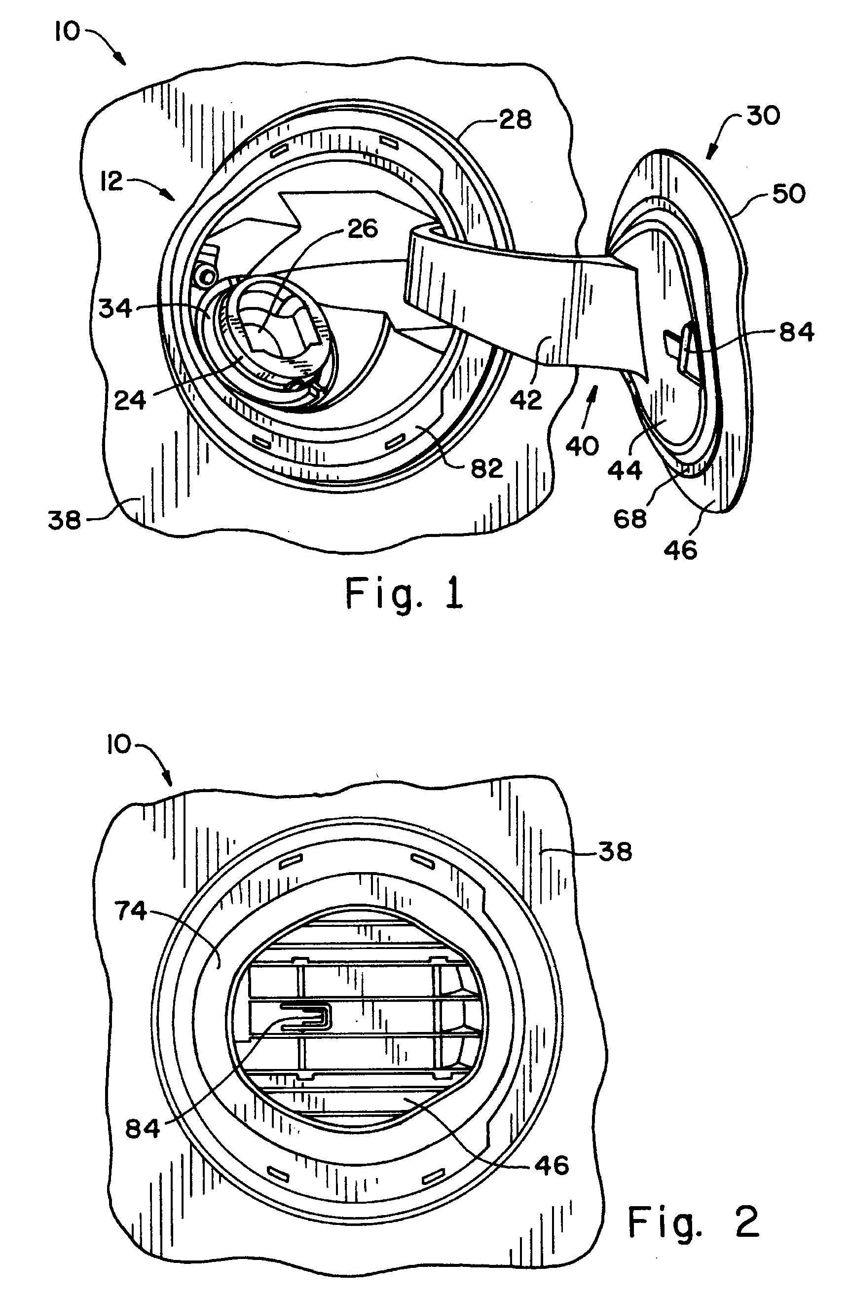
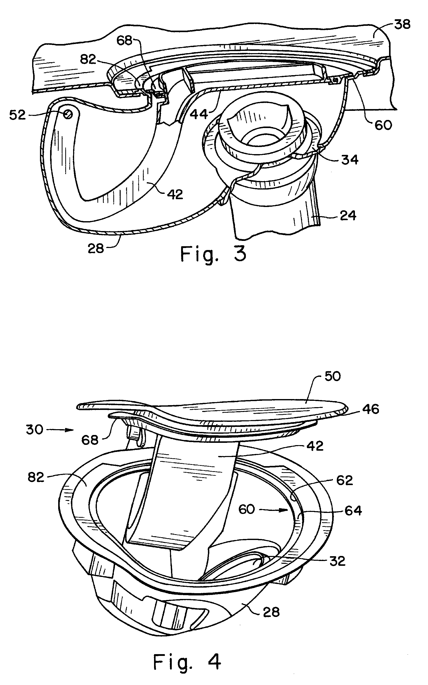
[0024]Referring now more specifically to the drawings and to FIG. 1 in particular, a fragmentary portion of a vehicle 20 is shown having a refueling assembly 22 therein. Refueling assembly 22 includes an inlet pipe 24 having a shut off 26. Inlet pipe 24 is provided in flow communication with a vehicle fuel tank (not shown) to establish a path for dispensing fuel into the tank from a refueling pump. A refueling nozzle (not shown) is inserted through the distal end of inlet pipe 24, which action opens shut off 26 as the nozzle is inserted therethrough. The distal end of inlet pipe 24 is accessed within a housing 28 having a door assembly 30 that can be opened and closed to expose and cover the end of inlet pipe 24.

[0025]It should be understood that the structures shown in the drawings are exemplary, and the forms and shapes of housing 28 and door assembly 30, as well as the location for inlet pipe 24 within housing 28 can be different from that shown. For example, while a generally ro...


PUM


Abstract

A vehicle refueling assembly includes a housing through which an inlet pipe is accessed and a door assembly that can be opened and closed relative to the housing. The door assembly includes a hinge and a decorative panel. The hinge includes a seal received in a ledge of the housing when the door assembly is closed.

Description

CROSS-REFERENCE TO RELATED APPLICATIONS[0001]The present regular United States patent application claims the benefits of U.S. Provisional Application Ser. No. 61 / 023,549 filed on Jan. 25, 2008 and of U.S. Provisional Application Ser. No. 61 / 045,659 filed on Apr. 17, 2008.FIELD OF THE INVENTION[0002]The present invention relates to fuel systems for motor vehicles and, more specifically, the invention pertains to fuel pipe and housing assemblies of the fuel system and seals for protecting fuel in the fuel system from contaminants.BACKGROUND OF THE INVENTION[0003]Fuel systems for motor vehicles are known to include a fuel tank and a filler tube having an inlet through which fuel is dispensed into the tank. It is known to use a removable cap at the end of the filler tube to close the tube. It is known also to use a movable damper and a rubber seal to close the fuel system either as the primary shutoff valve or as a secondary, supplemental shut-off structure. Capless refueling systems ar...

Claims


Application Information

Patent Timeline
Patent Type & Authority Applications(United States)
IPC IPC(8): B62D25/00
CPCB60K15/05B60K2015/0419B60K2015/03447
Inventor GURTATOWSKI, CRAIG W.RODAWOLD, JR., JOSEPH L.WOODWORTH, JACOB S.
Owner ILLINOIS TOOL WORKS INC
Why Eureka
Try Eureka