Amorphous transformer for electric power supply

a transformer and transformer technology, applied in the field of transformers, can solve problems such as stress and worsening of magnetic properties, and achieve the effects of high saturation magnetic flux density, superior properties, and reduced loss

Inactive Publication Date: 2009-07-30
HITACHI IND EQUIP SYST CO LTD
View PDF8 Cites 9 Cited by
  • Summary
  • Abstract
  • Description
  • Claims
  • Application Information

AI Technical Summary

Benefits of technology

[0021]According to the present invention, for an amorphous alloy having a composition of FeSiBC (Fe: iron, Si: silicon, B: boron, and C: carbon) different from that of conventional common materials wherein the amorphous alloy has a high s...

Problems solved by technology

However, in the wound iron core structure, stress to wo...

Method used


Image

  • Amorphous transformer for electric power supply
  • Amorphous transformer for electric power supply
  • Amorphous transformer for electric power supply

Examples


example 1

[0024]Example 1 will be described. An amorphous transformer for electric power supply according to this example contains an iron core, in which amorphous alloy foil bands are laminated and bent in a U-shape and both ends of the amorphous alloy foil bands are butted or overlapped, and a winding.

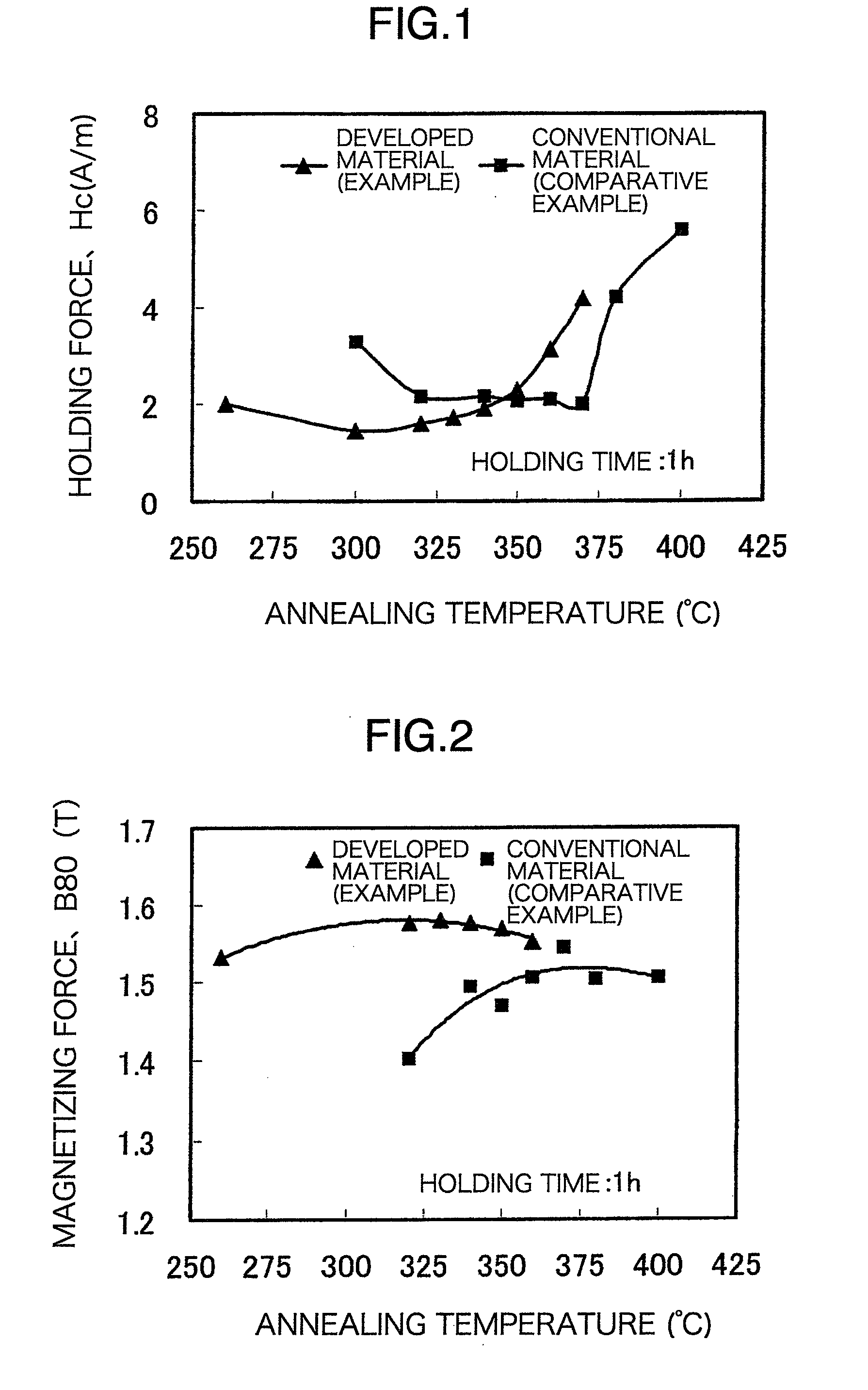
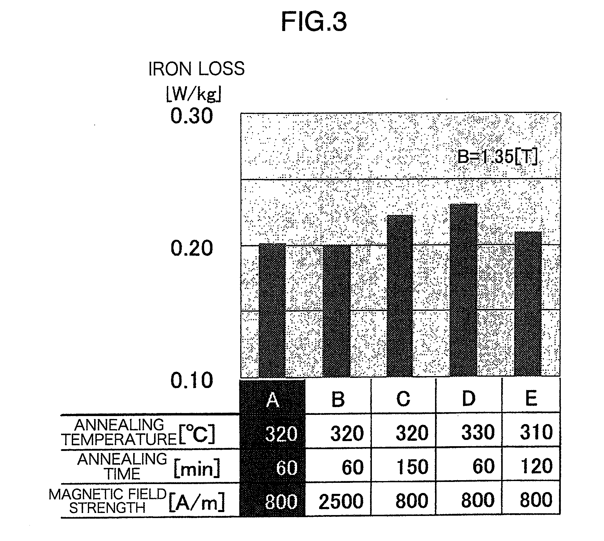
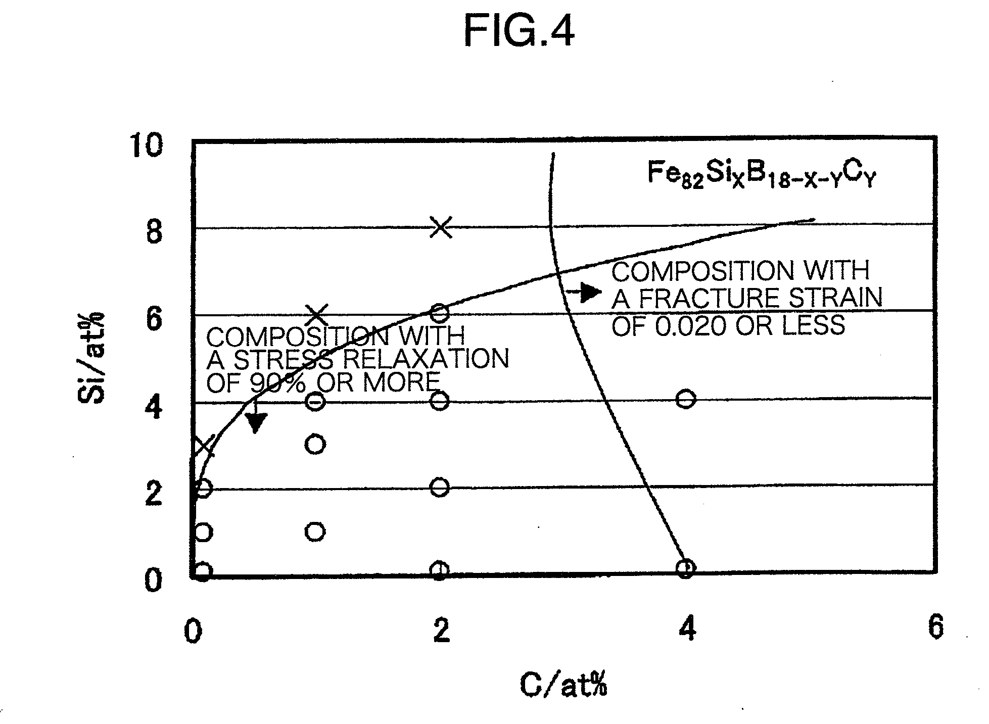
[0025]An amorphous alloy thin band used for the iron core of this example contains an amorphous alloy composed of an alloy composition expressed by FeaSibBcCd (Fe: iron, Si: silicon, B: boron, and C: carbon) in which 80≦a≦83%, 0

example 2

[0031]Next, Example 2 will be described. The amorphous transformer of this Example 2 differs from Example 1 in the material of the amorphous alloy thin band. The amorphous alloy thin band of Example 2 contains an amorphous alloy composed of an alloy composition expressed by FeaSibBcCd (Fe: iron, Si: silicon, B: boron, and C: carbon) in which 80≦a≦83%, 0


PUM

PropertyMeasurementUnit
Temperatureaaaaaaaaaa
Timeaaaaaaaaaa
Auxiliary magnetic fieldaaaaaaaaaa

Abstract

This invention provides an amorphous transformer for electric power supply, using a magnetic core formed of an amorphous alloy material, which, as compared with the conventional amorphous alloy material, has a lower annealing temperature and a higher level of magnetic properties. The amorphous transformer for electric power supply is provided with a magnetic core of a thin band of an amorphous alloy and a winding wire. The iron core has been annealed under such conditions that the iron core center part temperature during annealing after iron core molding is 300 to 340° C. and the holding time is not less than 0.5 hr. Further, for the iron core, the magnetic field intensity during annealing after the iron core molding is not less than 800 A/m.

Description

TECHNICAL FIELD[0001]The present invention relates to a transformer containing an iron core composed of an amorphous alloy thin band and a winding, and particularly to an amorphous transformer for electric power supply characterized by the material of the iron core and the annealing treatment of the iron core.BACKGROUND ART[0002]Conventionally, an amorphous transformer using an amorphous alloy as the material of the iron core is known. In this amorphous transformer, amorphous alloy foil bands are laminated and bent in a U-shape, and both ends of the amorphous alloy foil bands are butted or overlapped to provide a wound iron core, and the iron loss can be smaller than that of transformers using conventional electromagnetic steel sheets.[0003]However, in the wound iron core structure, stress to worsen the magnetic properties occurs when the material is bent. Therefore, it is necessary to subject the iron core to annealing treatment in a magnetic field to release the stress in order to...

Claims


Application Information

Patent Timeline
IPC IPC(8): H01F17/04C22C45/02H01F1/04
CPCC21D8/1244C21D2201/03H01F41/0226H01F1/15308C22C45/02
Inventor FUKUI, KAZUYUKIYAMASHITA, KOJIOGAWA, YUICHINAOE, MASAMUYOSHIZAWA, YOSHIHITO
Owner HITACHI IND EQUIP SYST CO LTD
Why Eureka
Try Eureka