Metal Magnetic Material And Electronic Component

a technology of metal magnetic materials and electronic components, applied in the direction of magnetic bodies, inductances, transportation and packaging, etc., can solve the problems of increasing the loss of an end product, the insufficient insulation resistance of the material itself, and the addition of glass, etc., to achieve easy oxidation, high saturation magnetic flux density, and easy oxidation

Active Publication Date: 2017-02-09
MURATA MFG CO LTD
View PDF3 Cites 0 Cited by
  • Summary
  • Abstract
  • Description
  • Claims
  • Application Information

AI Technical Summary

Benefits of technology

[0032]In the first aspect of the present invention, an additional element is added to a metal magnetic alloy powder consisting of iron and silicon or containing iron, silicon and chromium, wherein the additional element is more easily oxidizable in an equilibrium state of oxidation-reduction reaction than the elements contained in the metal magnetic alloy powder. This makes it possible to allow a metal magnetic material to reliably establish insulation while realizing high saturation magnetic flux density.
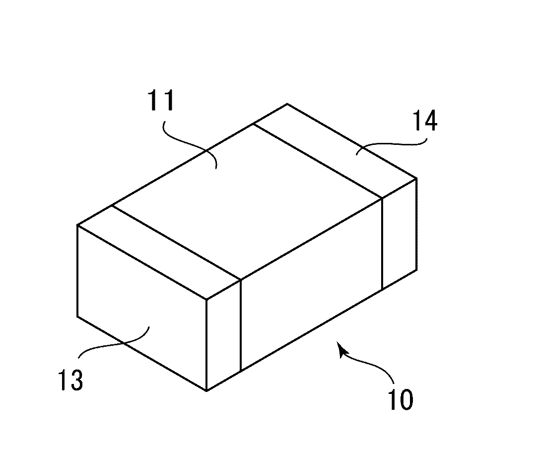
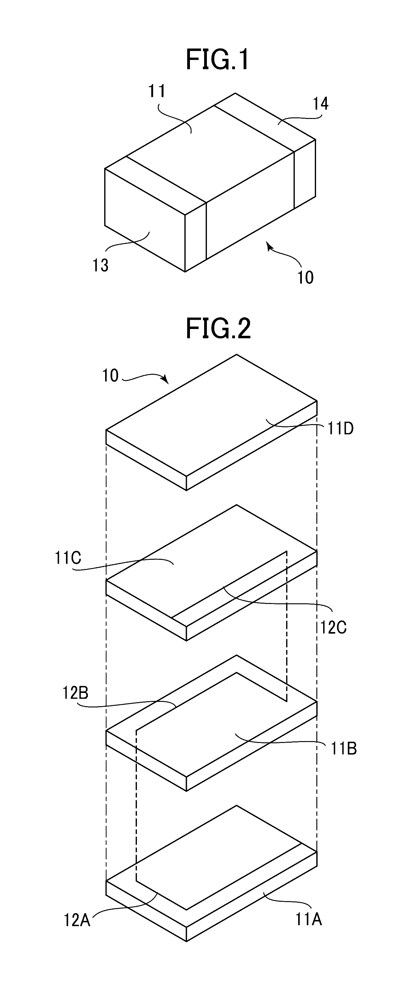
[0033]In the second aspect of the present invention, a component body is formed using a metal magnetic material, and a coil is formed inside or on a surface of the component body, wherein the metal magnetic material comprises a metal magnetic alloy powder consisting of iron and silicon or containing iron, silicon and chromium, and an additional element added to the metal magnetic alloy powder, wherein the additional element is more easily oxidizable in an equilibrium state of oxidation-reduction reaction than the elements contained in the metal magnetic alloy powder; and wherein the component body internally includes a reaction product of the metal magnetic alloy powder and the additional element which is more easily oxidizable in an equilibrium state of oxidation-reduction reaction than the elements contained in the metal magnetic alloy powder. This makes it possible to allow an electric component to have low loss and good DC superimposition characteristics.

Problems solved by technology

Although the metal magnetic material has an advantage of exhibiting a high saturation magnetic flux density, an insulation resistance of the material itself is insufficiently low.
If it fails to ensure the insulation, a component body of the electric component is electrically conducted to surroundings, or material properties of the metal magnetic material are degraded, thereby leading to an increase in loss in an end product.
This leads to problems such as a need to increase an addition amount of the glass, and an increase in cost for coating the particles.
As above, the conventional technique of bonding the particles together by a resin or the like or coating each of the particles with an insulating film has a problem that the amount of an insulating material other than the metal magnetic material has to be increased so as to more reliably ensure insulation performance, and the increase in volume of a material other than the metal magnetic material leads to degradation in magnetic properties.
However, in some cases, such an insulating film made of an oxide originating from only a raw material composition of particles of a metal magnetic material, as used in the above technique, exhibits poor insulation performance or fails to obtain sufficient strength.
However, the technique based on the impregnation or the like is poor in practicality because it causes not only an increase in cost but also a lack of stability in product quality.
Thus, as with the aforementioned conventional technique of coating each particle with an insulating film, there are problems such as an increase in cost, and an increase in amount of a coating material (shell-forming material), leading to degradation in magnetic properties.
However, each of the conventional techniques has some sort of problem, as mentioned above.

Method used


Image

  • Metal Magnetic Material And Electronic Component
  • Metal Magnetic Material And Electronic Component
  • Metal Magnetic Material And Electronic Component

Examples


Embodiment Construction

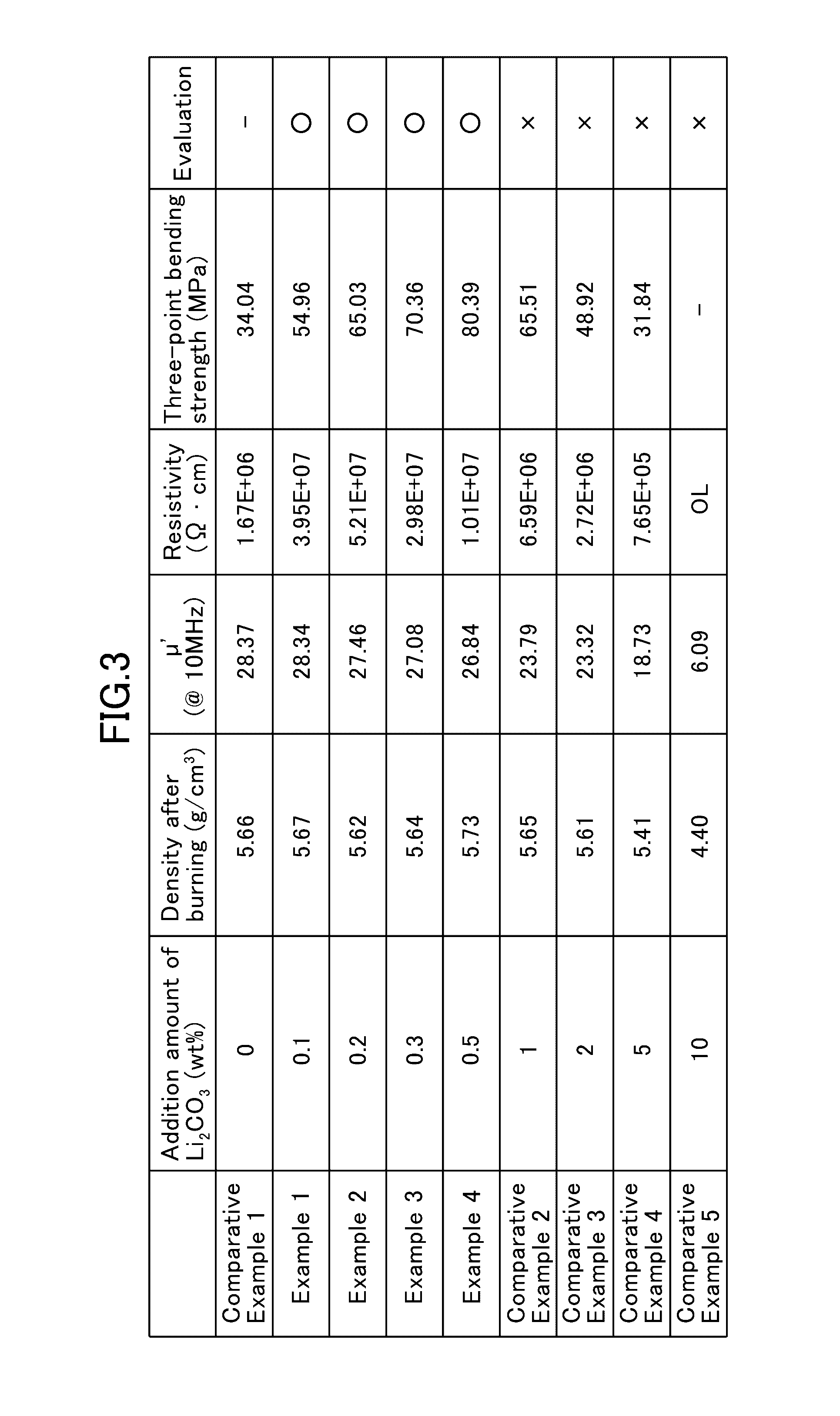
[0043]According to one embodiment of the present invention, there is provided a metal magnetic material which comprises a metal magnetic alloy powder consisting of iron and silicon or containing iron, silicon and chromium, and an additional element added to the metal magnetic alloy powder, wherein the additional element is more easily oxidizable in an equilibrium state of oxidation-reduction reaction than the elements contained in the metal magnetic alloy powder. Lithium may be used as the additional element which is more easily oxidizable in an equilibrium state of oxidation-reduction reaction than the elements contained in the metal magnetic alloy powder. When the metal magnetic material is subjected to a heat treatment, a reaction product of at least one of the elements of the metal magnetic alloy powder and lithium as the additional element which is more easily oxidizable in an equilibrium state of oxidation-reduction reaction than the elements contained in the metal magnetic al...


PUM

PropertyMeasurementUnit
volume resistivityaaaaaaaaaa
bending strengthaaaaaaaaaa
temperatureaaaaaaaaaa

Abstract

Provided are: a metal magnetic material capable of reliably establishing insulation while realizing high saturation magnetic flux density; and an electronic component using the metal magnetic material and having low loss and good DC superimposition characteristics. The metal magnetic material for forming a component body of the electronic component comprises a metal magnetic alloy powder consisting of iron and silicon or containing iron, silicon and chromium; and an additional element added to the metal magnetic alloy powder, wherein the additional element is more easily oxidizable in the equilibrium state of oxidation-reduction reaction than the elements contained in the metal magnetic alloy powder. The component body (11) is internally formed with a coil pattern consisting of a plurality of coil conductor patterns (12A to 12C). The metal magnetic material is less likely to undergo degradation in magnetic properties even after it is subjected to a heat treatment at a high temperature, so that it becomes possible to perform a heat treatment for reducing a resistance of the coil pattern, at an adequate temperature.

Description

TECHNICAL FIELD[0001]The present invention relates to a metal magnetic material usable for a power inductor or other component for use in an electric circuit.BACKGROUND ART[0002]A power inductor for use in a power supply circuit is required to achieve smaller size and lower loss and cope with a large current. With a view to meeting such requirements, it is being studied to use, as a magnetic material for the power inductor, a metal magnetic material having a high saturation magnetic flux density. Although the metal magnetic material has an advantage of exhibiting a high saturation magnetic flux density, an insulation resistance of the material itself is insufficiently low. Thus, as a prerequisite for allowing the metal magnetic material to be used as a magnetic material for an electric component, it is necessary to ensure insulation between particles of the metal magnetic material. If it fails to ensure the insulation, a component body of the electric component is electrically condu...

Claims


Application Information

Patent Timeline
Patent Type & Authority Applications(United States)
IPC IPC(8): H01F1/03B22F1/02H01F27/255C22C38/18C22C38/02C22C38/00B22F1/00C21D6/00B22F1/12B22F1/142B22F1/16
CPCH01F1/0306B22F1/0003B22F1/02C21D6/002C21D6/008C22C38/18C22C38/02C22C38/002H01F27/255B22F2302/45B22F1/00H01F1/24H01F1/33H01F17/0013B22F2998/10B22F1/142B22F1/16B22F1/12B22F1/10B22F3/10B22F3/1021
Inventor YAMAMOTO, MAKOTO
Owner MURATA MFG CO LTD
Why Eureka
Try Eureka