
Scroll compressor improved in function of oil circulation and back pressure control

a compressor and back pressure technology, applied in the field of roller compressors, can solve the problems of complex apparatus, difficult manufacturing process, and inability to adjust the back pressure of coolant gas, and achieve the effect of improving the function of oil circulation and back pressure control and facilitating the lubrication of inner components

Active Publication Date: 2009-07-30
DOOWON TECHN COLLEGE +1
View PDF1 Cites 24 Cited by
  • Summary
  • Abstract
  • Description
  • Claims
  • Application Information

AI Technical Summary

Benefits of technology

[0013]In order to solve the problems, it is an object of the present invention to provide a scroll compressor having an improved function of oil circulation and back pressure control capable of readily performing lubrication of inner components and simultaneously maintaining a predetermined back pressure using an oil circulation structure.
[0014]It is another object of the present invention to provide a scroll compressor having an improved function of oil circulation and back pressure control capable of readily separating oil from coolant in the front of a housing.
[0015]It is still another object of the present invention to provide a scroll compressor having an improved function of oil circulation and back pressure control capable of securely maintaining axial sealing even when a back pressure varies.Technical Solution

Problems solved by technology

However, the coolant gas can only adjust a back pressure, and an apparatus for performing an oil circulation function such as lubrication still needs to be separately provided.
As a result, the apparatus is complicated and its manufacturing process is very difficult.
In addition, since the stationary scroll is axially moved toward the orbiting scroll due to the back pressure, its structure is unstable and its vibration increases.

Method used


Image

  • Scroll compressor improved in function of oil circulation and back pressure control
  • Scroll compressor improved in function of oil circulation and back pressure control
  • Scroll compressor improved in function of oil circulation and back pressure control

Examples


Embodiment Construction

[0040]Reference will now be made in detail to exemplary embodiments of the present invention illustrated in the accompanying drawings.

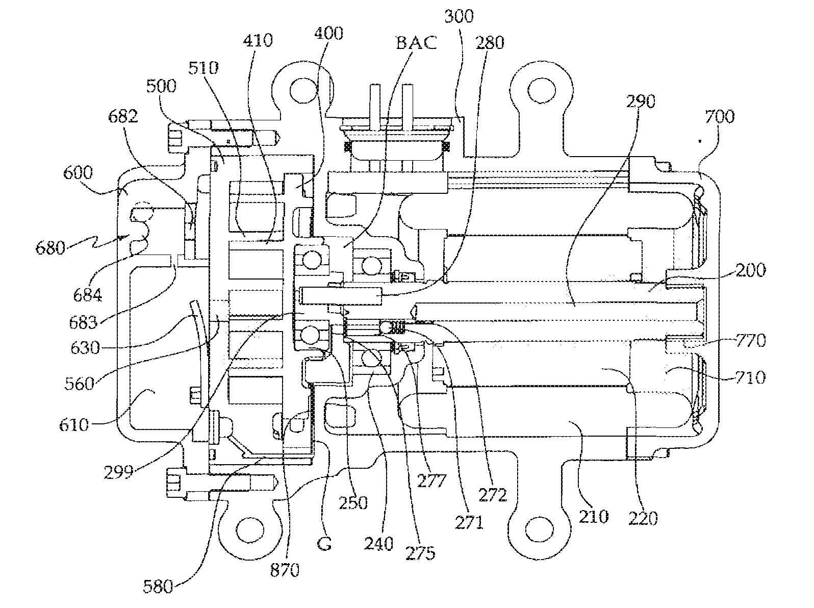
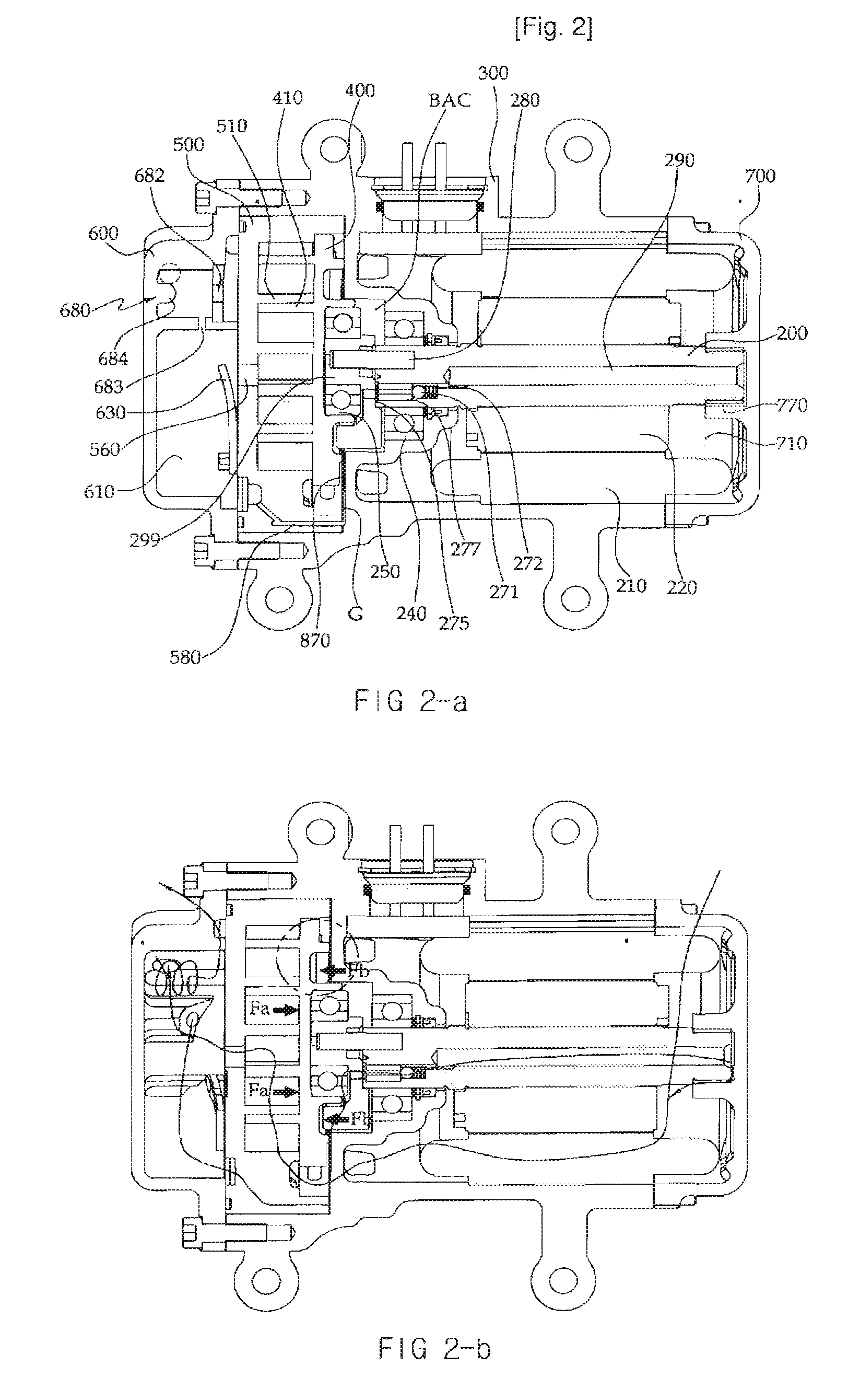
[0041]As shown in FIG. 2, a scroll compressor having an improved function of oil circulation and back pressure control in accordance with an exemplary embodiment of the present invention includes: a housing H; a drive part for generating a rotational force; a drive shaft 200 driven by the drive part; and a scroll compression part having a stationary scroll 500 fixed regardless of rotation of the drive shaft 200 and having a scroll wrap 510 for compressing sucked fluid, and an orbiting scroll 400 orbited depending on rotation of the drive shaft 200 and having a spiral scroll wrap 410.

[0042]Here, a discharge hole 650 and a discharge chamber 610 are formed at a front part 600 of the housing H, a passage through which coolant passes is formed at an intermediate part 300 of the housing H, and a suction hole 750 and a suction chamber 710 are formed at a rea...


PUM


Abstract

Provided is a scroll compressor having an improved function of oil circulation and back pressure control. The scroll compressor includes: a housing; a drive part for generating a rotational force; a drive shaft driven by the drive part; and a scroll compression part including a stationary scroll fixed regardless of rotation of the drive shaft and having a scroll wrap for compressing sucked fluid and a discharge port for supplying coolant into a discharge chamber, and an orbiting scroll orbited depending on rotation of the drive shaft and having a scroll wrap, characterized in that the coolant compressed by the scroll compression part is conveyed to the discharge chamber, the coolant of the discharge chamber is separated into oil and gas in an oil separator, the gas being discharged through a discharge hole and the oil being supplied into a back pressure chamber through a return path formed in the stationary scroll, and the oil is returned into a suction chamber through a back pressure adjustment valve.

Description

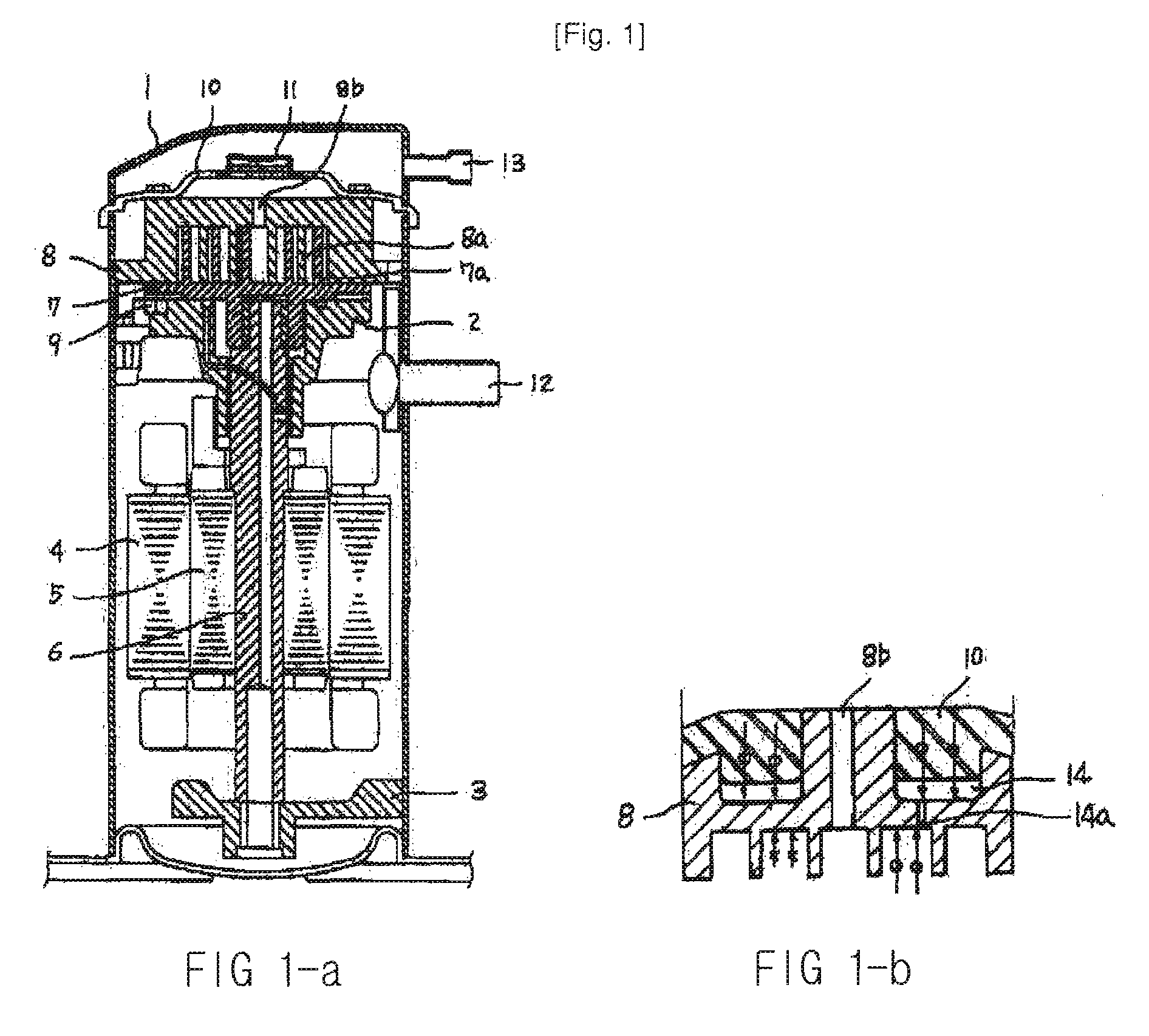
TECHNICAL FIELD[0001]The present invention relates to a scroll compressor having an improved function of oil circulation and back pressure control, and more particularly, to a scroll compressor having an improved function of oil circulation and back pressure control capable of simultaneously performing the oil circulation and back pressure control.BACKGROUND ART[0002]A conventional scroll compressor is disclosed in Korean Patent Laid-open Publication No. 1998-50613, which will be described with reference to FIG. 1.[0003]As shown, the conventional scroll compressor includes a sealing vessel 1, upper and lower frames 2 and 3 installed at upper and lower parts in the sealing vessel 1, a stator 4 fixedly installed between the upper and lower frames 2 and 3, a rotor 5 inserted into an inner periphery of the stator 4, a drive shaft 6 press?fitted into a center of the rotor 5 to pass through a center of the upper frame 2, and an orbiting scroll 7 eccentrically coupled with the drive shaft ...

Claims


Application Information

Patent Timeline
Patent Type & Authority Applications(United States)
IPC IPC(8): F04C18/02F04C29/12
CPCF04C18/0215F04C29/026F04C27/005F04C23/008Y10S418/01F04C18/02F04C29/02
Inventor LEE, GEONHONAM, DONG-LIMHAN, YOUNG-CHANGNAM, BO-YOUNGLEE, JUNG-KYUNG
Owner DOOWON TECHN COLLEGE
Learn More