
Radio communication system

Inactive Publication Date: 2009-07-30
FUJITSU LTD
View PDF14 Cites 13 Cited by
  • Summary
  • Abstract
  • Description
  • Claims
  • Application Information

AI Technical Summary

Benefits of technology

[0012]Accordingly, the objective of the present invention is to provide a radio communication system, preventing communication disconnection when a communication failure occurs in a base station.
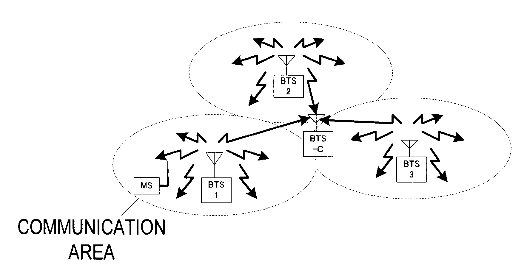
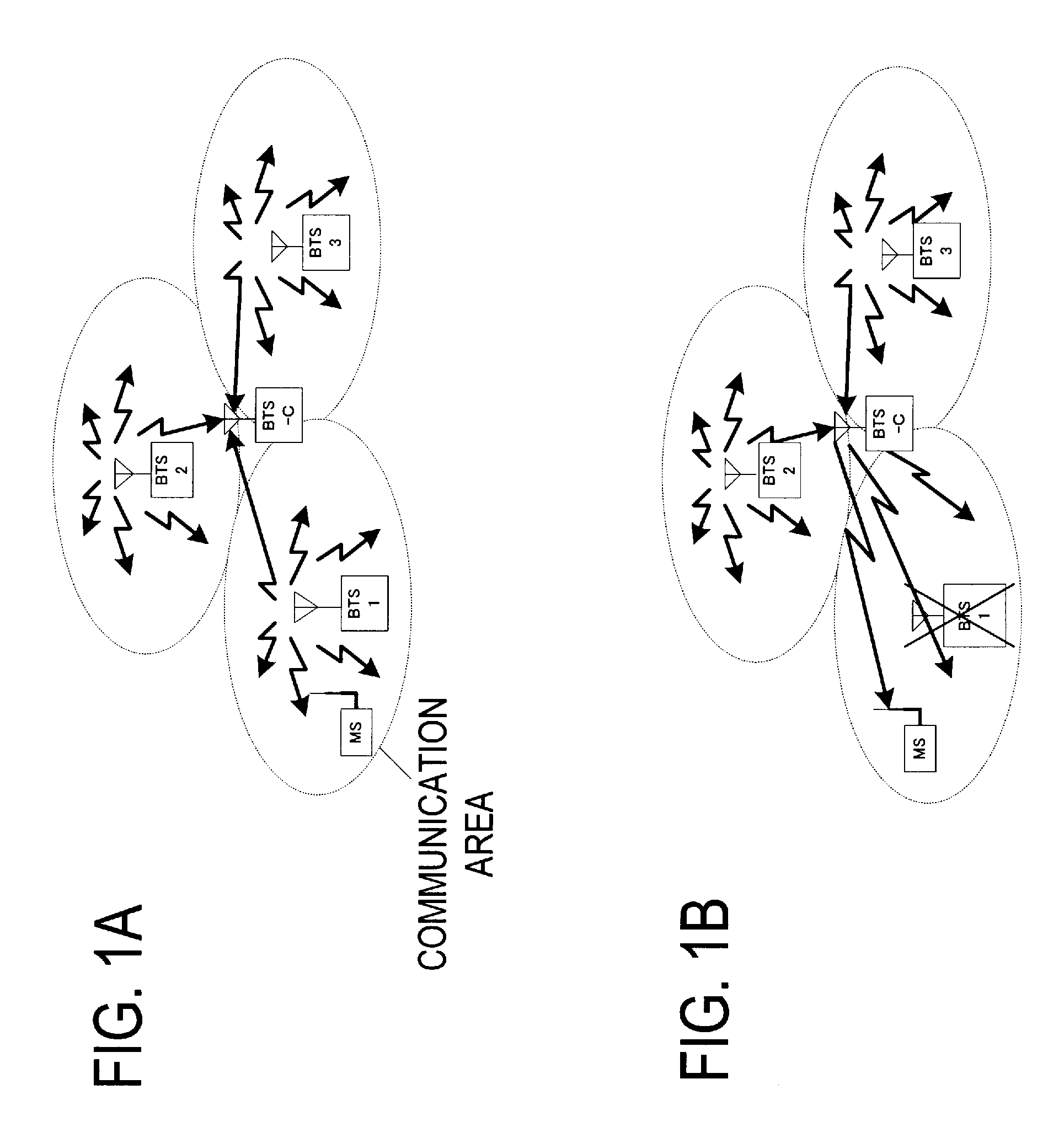
[0014]Even when the overall base station falls into a communication impossible condition, a communication interruption can be avoided by switching over to substitutional communication using the common base station. By providing one common base station to the plurality of base stations, the overall system cost can be reduced.
[0026]According to the present system, when the communication between the terminal and the base station falls into a communication impossible state, by switching the communication with the terminal to the common base station, the communication by the terminal can be continued without causing communication disconnection. Since the common base station is installed for the plurality of base stations, it becomes unnecessary to prepare redundant configuration for each base station, such as a duplicated equipment configuration, which leads to the reduction of overall system cost. Further, even when the base station falls into a communication impossible state due to the disconnection of the power or the disconnection of the communication path with the upper-level unit, etc., by operating the common base station as a substitutional communication means, the communication disconnection can be avoided, and a highly reliable radio communication system can be obtained.

Problems solved by technology

This produces an increase of an equipment scale with a complicated equipment configuration, such that processing to share data on the active side and the standby side becomes necessary.
Meanwhile, even when the equipment in the base station is configured of duplicated structure, unless a power unit to supply power to the base station is not duplicated, or a preferential communication path to an upper-level unit is not duplicated, the communication function of the base station itself goes down in the event of a failure in the above units, and communication in the base station communication area becomes impossible.
It is not possible to prevent the disconnection of the communication itself.
However, the above method is not realistic because of requiring a large cost to implement such the system.

Method used


Image

  • Radio communication system
  • Radio communication system
  • Radio communication system

Examples


Embodiment Construction

[0037]The preferred embodiment of the present invention is described hereinafter referring to the charts and drawings. However, it is noted that the embodiments described below do not intend to restrict the technical scope of the present invention.

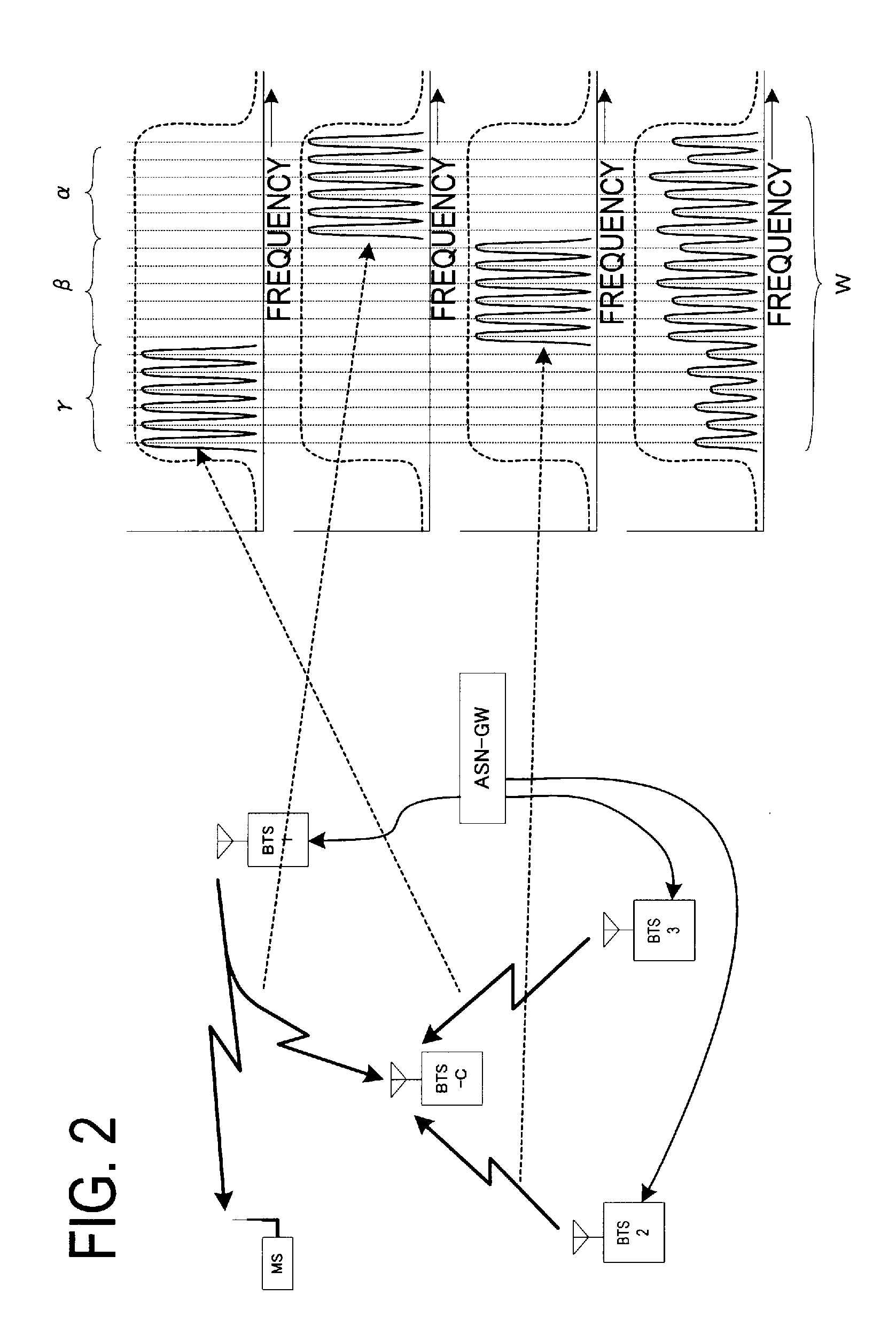
[0038]The radio communication system according to the embodiment adopts a multicarrier transmission scheme [for example, OFDM (Orthogonal Frequency Division Multiplexing): including OFDMA (Orthogonal Frequency Division Multiple Access)], by which communication performed by a plurality of base stations, each located in each communication area, is carried out using subcarriers in a frequency range not overlapped between the base stations having mutually adjacent communication areas. In the multicarrier transmission scheme, data are transmitted in parallel by being divided into a plurality of subcarriers. Since a symbol period can be made longer as compared to a single carrier transmission, transmission deterioration caused by multipath can b...


PUM


Abstract

A radio communication system, preventing communication disconnection when a communication failure occurs in a base station, is provided. The radio communication system includes a common base station (BTS-C) communicable with each communication area of the plurality of BTS (FIG. 1A), in addition to a plurality of base stations (BTS) each located in each communication area. In place of a base station BTS which becomes a communication impossible state with a terminal in the communication area, the BTS-C communicates with the terminal MS in the communication area concerned.

Description

CROSS-REFERENCE TO RELATED APPLICATIONS[0001]This application is based upon and claims the benefit of priority from the prior Japanese Patent Application No. 2008-016324, filed on Jan. 28, 2008, the entire contents of which are incorporated herein by reference.BACKGROUND OF THE INVENTION[0002]1. Field of the Invention[0003]The present invention relates to a radio communication system having a plurality of base stations each located in each communication area, and more particularly a radio communication system communicating between the base stations having adjacent areas, using frequencies which are not mutually overlapped.[0004]2. Description of the Related Art[0005]As a measure for avoiding a communication failure due to a trouble in a base station constituting the radio communication system, for example, there has been adopted a redundant configuration, such as a duplicated structure, in the equipment configuration of each base station.[0006]When the equipment has duplicated struc...

Claims


Application Information

Patent Timeline
IPC IPC(8): H04W88/00H04L45/24H04L45/586H04W16/24H04W24/04H04W92/20
CPCH04B7/022H04W76/04H04W24/04H04W76/20
Inventor SHIBATA, MANABU
Owner FUJITSU LTD
Learn More