Method and apparatus for time scaling of a signal

a time scale and signal technology, applied in the field of time scaling methods and apparatuses of audio signals, can solve the problems of increasing computational requirements, reducing the quality of time scaled signals, and introducing an additional amount of complexity, and achieve the effect of facilitating or enabling a reduced complexity time scaling decoder and efficient low-complex generation of stereo signals

Inactive Publication Date: 2009-07-30
KONINKLIJKE PHILIPS ELECTRONICS NV
View PDF11 Cites 18 Cited by
  • Summary
  • Abstract
  • Description
  • Claims
  • Application Information

AI Technical Summary

Benefits of technology

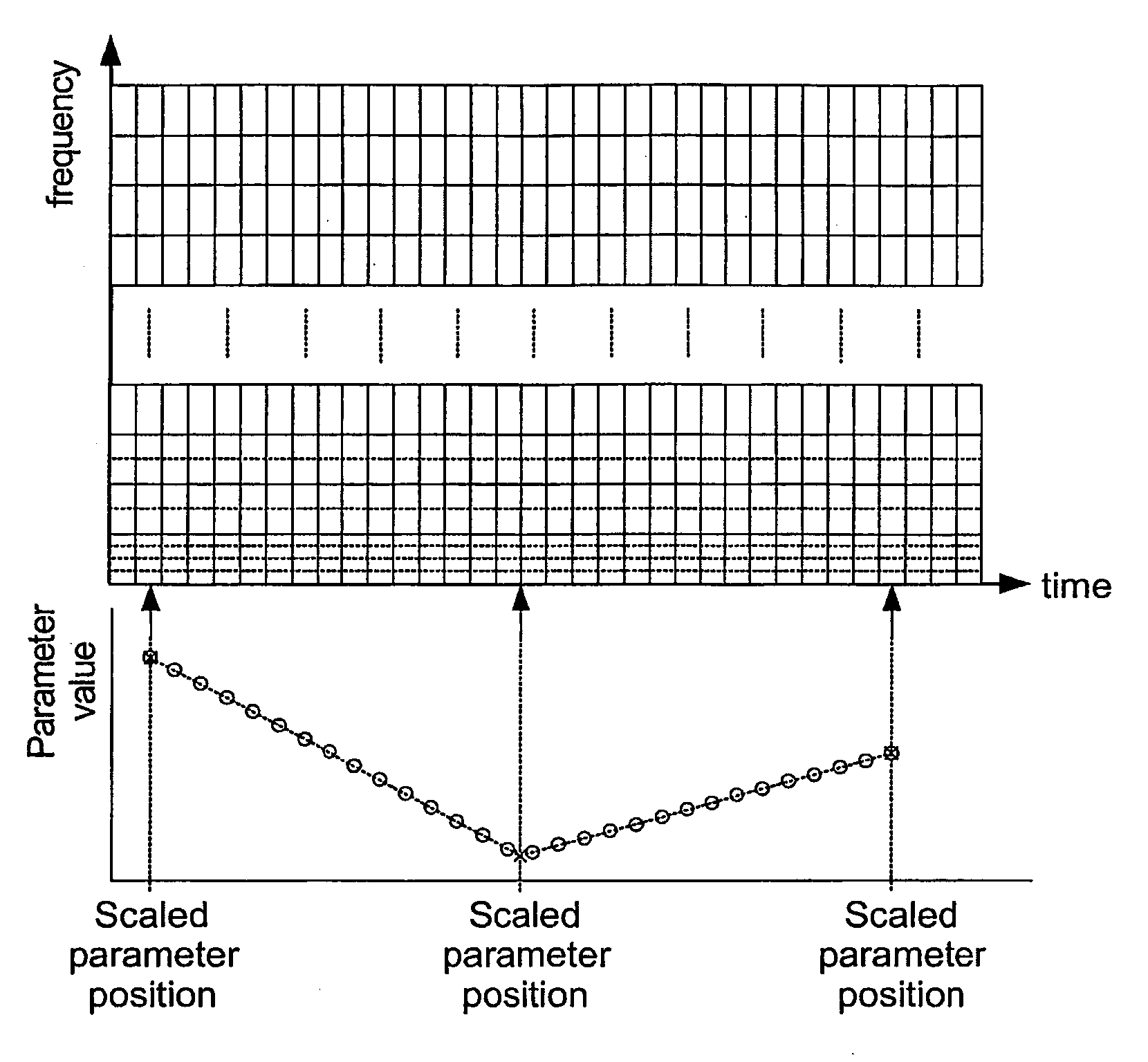
[0052]According to a different feature of the invention, the means for generating the frequency sample blocks comprise complex-exponential modulated filter banks (e.g. a QMF based filter bank). Similarly, the means for generating time domain output sample blocks preferably comprises complex-exponential modulated filter banks. The invention may thus facilitate or enable a reduced complexity time scaling decoder and in particular the requirement for analysis windowing in association with domain transforms may preferably be obviated.
[0053]According to a different feature of the invention, the extension data comprises parametric stereo data and preferably the first parameter value is a parameter value of a stereo image parameter sele

Problems solved by technology

Therefore, for conventional waveform coded material, an additional amount of complexity is introduced, as both regular decoding and complex time scaling processing must be performed.
Furthermore, time scale processing typically introduces artefacts into the decoded signal and therefore degrades t

Method used


Image

  • Method and apparatus for time scaling of a signal
  • Method and apparatus for time scaling of a signal
  • Method and apparatus for time scaling of a signal

Examples


Embodiment Construction

[0064]The following description focuses on an embodiment of the invention applicable to an audio time scaling decoder and in particular to an MPEG-4 Extension 2 stereo decoder comprising time scaling functionality. However, it will be appreciated that the invention is not limited to this application but may be applied to many other signals and applications.

[0065]It will be appreciated that although the specific description focuses on this embodiment, the principles, alternatives and features described herein are not necessarily limited to this specific embodiment but may optionally be applied to other suitable embodiments.

[0066]FIG. 5 illustrates a time scaling decoder 500 in accordance with an embodiment of the invention.

[0067]The time scaling decoder 500 comprises a receiver 501 which receives an MPEG-4 Extension 2 encoded stereo signal from an external or internal source (not shown). The receiver 501 may for example receive an MPEG-4 Extension 2 bitstream from a network connectio...


PUM


Abstract

A decoder receives (501) a bitstream comprising an encoded mono signal and stereo data. A time scale processor (503) generates a time scaled mono signal. A time-to frequency processor generates frequency sample blocks of the time scaled signal, the block length being fixed and independent of the time scaling. A parametric stereo decoder (509) generates a stereo signal for the frequency sample blocks and these are converted to the time domain by a frequency-to-time processor (511). A synchronization processor (515) synchronizes the stereo data with the time scaled signal by determining a time association between a parameter value and a frequency sample block. The parameter value and time association is used to determine synchronized stereo parameter values for that and other frequency sample blocks. The invention is particularly suitable for low complexity generation of time scaled stereo signals from MPEG-4 encoded signals.

Description

FIELD OF THE INVENTION[0001]The invention relates to a method and apparatus for time scaling of a signal and in particular to a method and apparatus for time scaling an audio signal.BACKGROUND OF THE INVENTION[0002]In recent years, the distribution and storage of A / V content in digital form has increased substantially. Accordingly, a large number of coding standards and protocols have been developed.[0003]Audio coding and compression techniques provide for very efficient audio encoding which allows audio files of relatively low data size and high quality to be conveniently distributed through data networks including for example the Internet.[0004]An example of a coding standard is the Motion Picture Expert Group-4 (MPEG-4) coding standard which provides decoder specifications for both video and audio coding. Further details of the MPEG-4 coding standard may be found in “Coding of Audio-Visual Objects”, MPEG-4: ISO / IEC 14496.[0005]A technique which may be applied to audio signals to ...

Claims


Application Information

Patent Timeline
IPC IPC(8): G10L19/00G10L19/008G10L21/04
CPCG10L21/04G10L19/008
Inventor SCHUIJERS, ERIK GOSUINUS PETRUSGERRITS, ANDREAS JOHANNESOOMEN, ARNOLDUS WERNER JOHANNES
Owner KONINKLIJKE PHILIPS ELECTRONICS NV
Why Eureka
Try Eureka