
Electronic health record timeline and the human figure

Active Publication Date: 2009-07-30
GENERAL ELECTRIC CO
View PDF31 Cites 126 Cited by
  • Summary
  • Abstract
  • Description
  • Claims
  • Application Information

AI Technical Summary

Benefits of technology

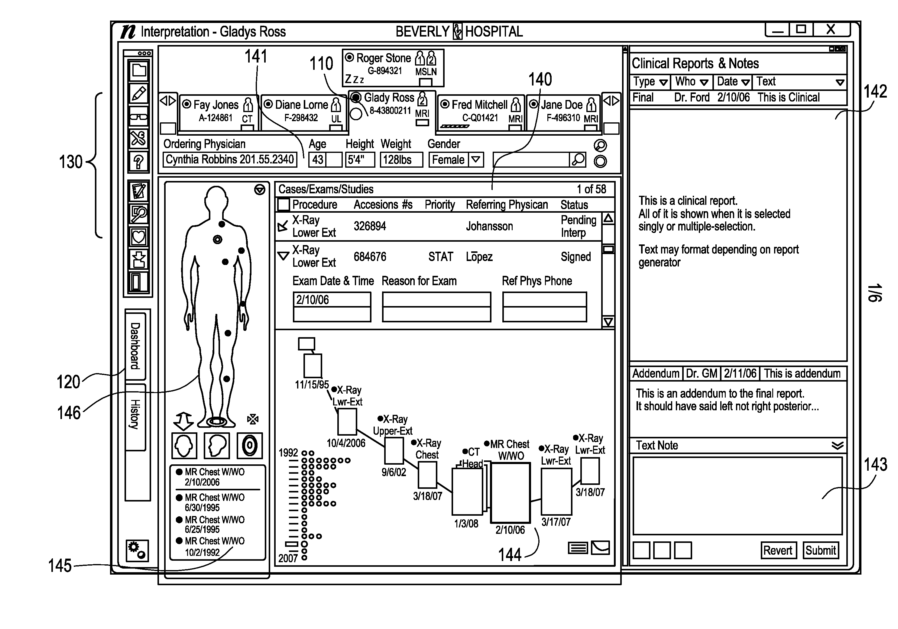
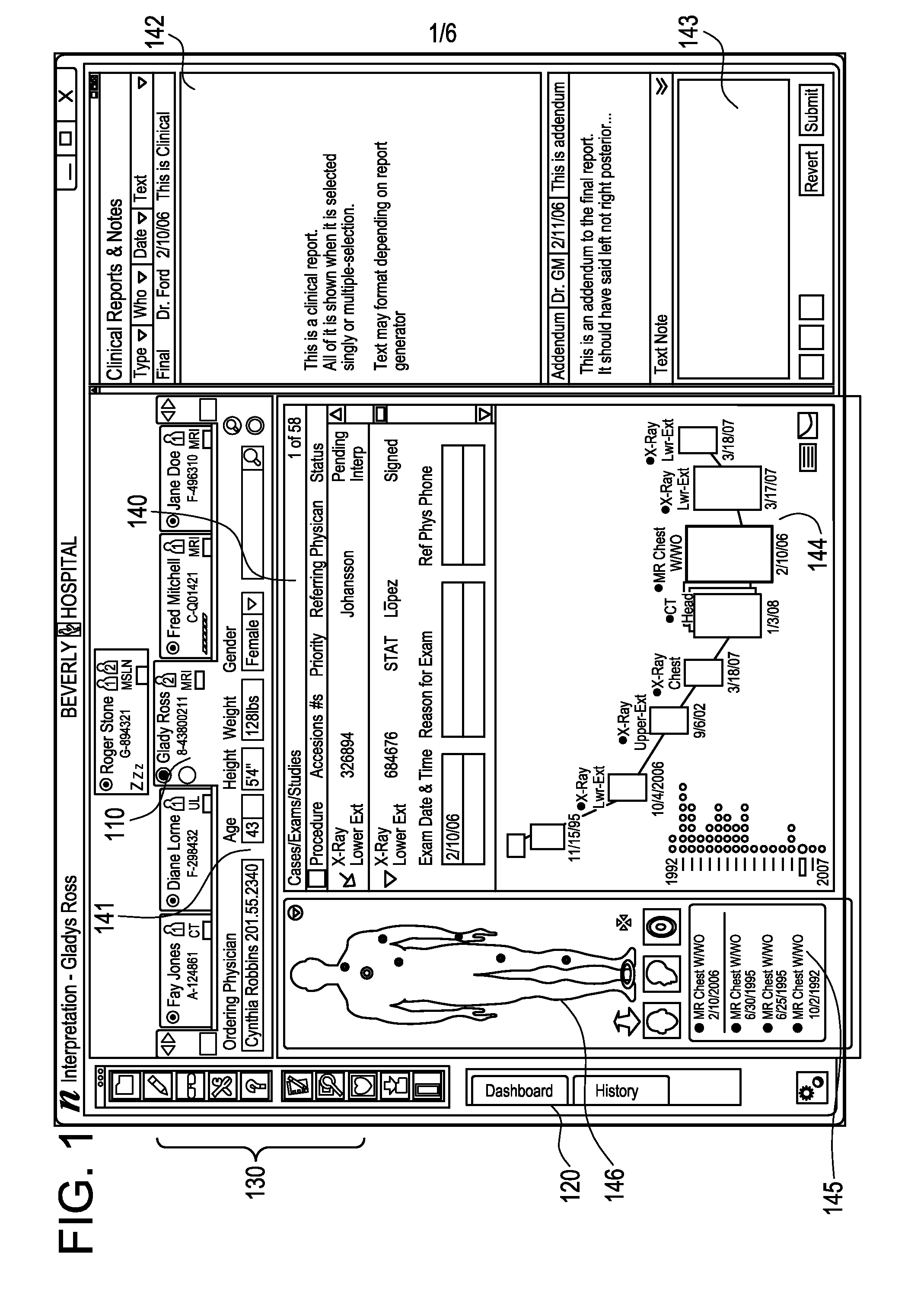
[0013]Certain embodiments provide a method for aggregating and displaying a graphical view of patient anatomy and history. The method includes compiling patient information from a plurality of clinical information sources and identifying clinical events related to the patient based on the patient information. The method also includes graphically displaying the compiled patient information using both a graphical representation of at least a portion of a human anatomy and an electronic health record timeline of clinical events for the patient. Each of the representation and the timeline include corresponding sets of one or more indicators identifying clinical events that have occurred in connection with the patient. Each of the one or more indicators is located at an anatomical location on the graphical representation affected by the clinical event corresponding to the indicator and located on the timeline at a point in time at which the clinical event occurred. The method further includes facilitating user interaction with the displayed patient clinical event indicators on both the graphical representation and the timeline. A selection or change of an indicator on one of the graphical representation or the electronic health record timeline triggers a corresponding selection or change of the indicator on the other of the graphical representation or the electronic health record timeline.
[0014]Certain embodiments provide a machine readable medium having a set of instructions for execution on a computing device. The set of instructions, when executed on the computing device, cause the computing device to execute a method for aggregating and displaying a graphical view of patient anatomy and history. The method includes compiling patient information from a plurality of clinical information sources and identifying clinical events related to the patient based on the patient information. The method also includes graphically displaying the compiled patient information using both a graphical representation of at least a portion of a human anatomy and an electronic health record timeline of clinical events for the patient. Each of the representation and the timeline include corresponding sets of one or more indicators identifying clinical events that have occurred in connection with the patient. Each of the one or more indicators is located at an anatomical location on the graphical representation affected by the clinical event corresponding to the indicator and located on the timeline at a point in time at which the clinical event occurred. The method further includes facilitating user interaction with the displayed patient clinical event indicators on both the graphical representation and the timeline. A selection or change of an indicator on one of the graphical representation or the electronic health record timeline triggers a corresponding selection or change of the indicator on the other of the graphical representation or the electronic health record timeline.

Problems solved by technology

In recent history, a reading physician was naturally limited to few sources of such clinical data including probably a film jacket of one to three prior studies and other clinical evidence printed on an exam requisition form.
Such principal availability of extensive clinical history presents a serious challenge to ergonomic design of diagnostic workstations that allow easy and effective search and navigation within a multiplicity of clinical evidence to facilitate productivity of diagnostic reading without risk of missing an important piece of clinical evidence which loss or neglecting can substantially change diagnostic conclusion or affect important details of a diagnostic report.

Method used


Image

  • Electronic health record timeline and the human figure
  • Electronic health record timeline and the human figure
  • Electronic health record timeline and the human figure

Examples


Embodiment Construction

[0022]Certain embodiments provide a single view of a patient's full medical record across specialties in an aggregate, graphical format that enables a user to drill down for additional information and to determine severity within an anatomic structure for a patient over time.

[0023]In prior systems, users have had difficulty in viewing patient's record even when all data is present. There is no facility for determining severity of chronic patient issues. It has not been easy to see, in a single view, a patient's full health record across specialties. Even when a patient's clinical data is provided, most electronic medical records (“EMRs”) or electronic health records (“EHRs”) provide separate sections for radiology, cardiology, labs, etc., that are not aggregated in a single view so that you know immediately what's going on with the patient. Prior systems failed to provide a capability to determine a severity within an anatomic structure for a patient by time, for example.

[0024]Certa...


PUM


Abstract

A patient information interface system presents an aggregated, graphical view of patient anatomy and history. The system includes a graphical representation of at least a portion of a human anatomy including one or more indicators, aggregated from a plurality of clinical information sources and located at anatomical locations on the representation, that correspond to clinical events that have occurred in connection with a patient. The system also includes an electronic health record timeline of clinical events for the patient. The timeline includes the same one or more indicators that are displayed on the graphical representation corresponding to clinical events that have occurred in connection with a patient. A selection or change of an indicator on one of the graphical representation or the electronic health record timeline triggers a corresponding selection or change of the indicator on the other of the graphical representation or the electronic health record timeline.

Description

RELATED APPLICATIONS[0001]The present application claims the benefit of priority as a continuation-in-part to U.S. patent application Ser. No. 12 / 110,053, filed on Apr. 25, 2008, entitled “Systems and Methods for Presentation of Clinical Evidence for Diagnostic Interpretation,” which claims the benefit of priority to U.S. Provisional Application No. 60 / 926,356, filed on Apr. 26, 2007, entitled “Special Methodics for Optimal Presentation of the Clinical Evidences for Diagnostic Interpretation”, each of which is herein incorporated by reference in its entirety.FEDERALLY SPONSORED RESEARCH OR DEVELOPMENT[0002][Not Applicable]MICROFICHE / COPYRIGHT REFERENCE[0003][Not Applicable]FIELD OF INVENTION[0004]The presently described technology relates to graphical display of patient information. More specifically, the presently described technology relates to aggregation and graphical display of patient information in a single interface.BACKGROUND OF THE INVENTION[0005]Healthcare environments, s...

Claims


Application Information

Patent Timeline
IPC IPC(8): G06Q50/00G06F3/048G16Z99/00
CPCG06F19/321G06F19/322G06Q50/24G06Q10/06G06Q50/22G06F19/3487G16H10/60G16H15/00G16H30/40G16Z99/00G16H10/40G16H30/20
Inventor HAWKINS, MICHAELPAVLOV, DMITRYBURT, CHRISTOPHERLOPEZ, KENNETHSIDDIQUI, KHAN
Owner GENERAL ELECTRIC CO
Learn More