Shooting bow

a trigger assembly and shooting bow technology, applied in the direction of compressed gas guns, white arms/cold weapons, weapons, etc., can solve the problems of unanticipated early or late release of the string during the trigger pull, undesirably hard and rough trigger pull, etc., to achieve a smoother actuation of the firing assembly

Inactive Publication Date: 2009-08-06
KEMPF JAMES J
View PDF38 Cites 63 Cited by
  • Summary
  • Abstract
  • Description
  • Claims
  • Application Information

AI Technical Summary

Benefits of technology

[0006]In an advantage provided by this invention, a trigger assembl

Problems solved by technology

Tension associated with prior art devices and the solid engagement of the sear with the trigger assembly often results in an undesirably hard and rough trigger pull.
This tensi

Method used


Image

  • Shooting bow
  • Shooting bow
  • Shooting bow

Examples


Embodiment Construction

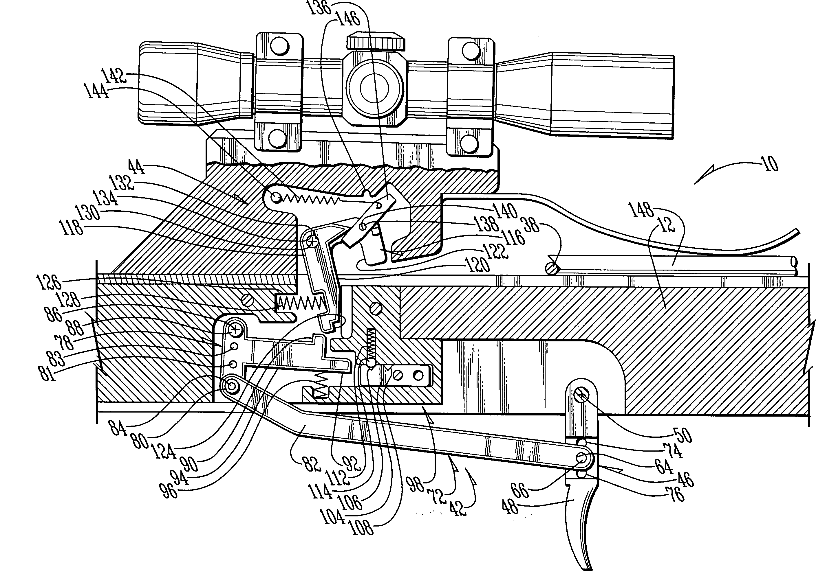
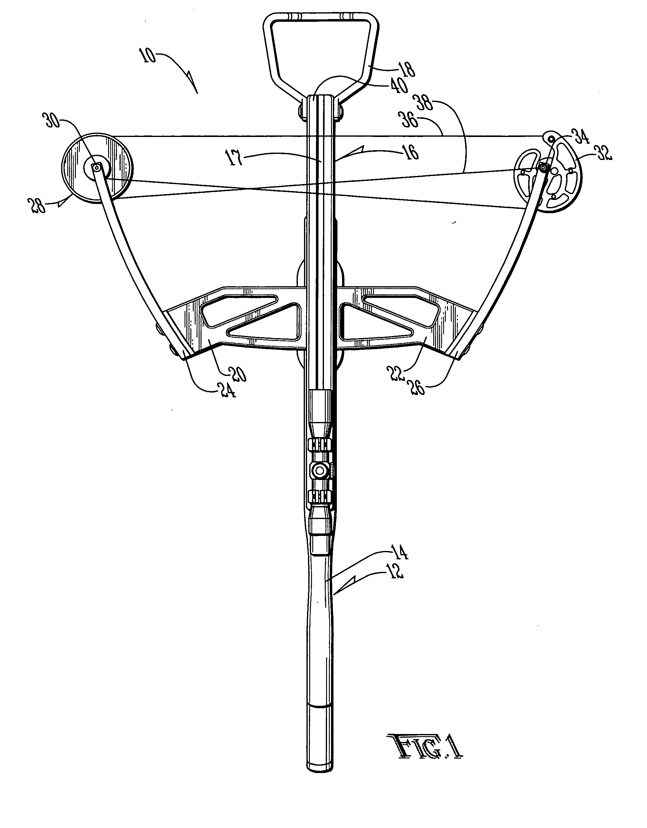
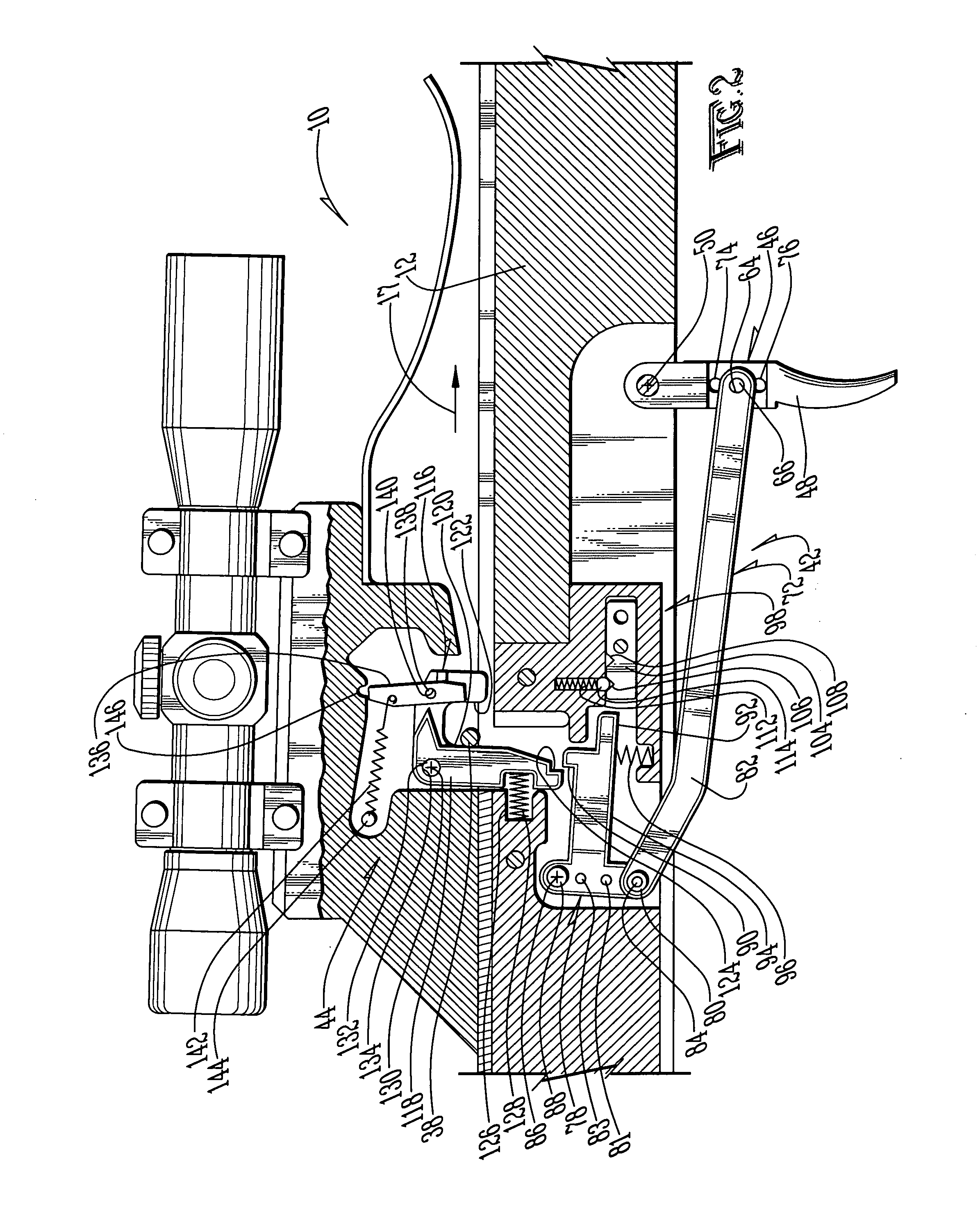
[0023]A crossbow is shown generally as (10) in FIG. 1. The crossbow (10) is provided with a frame (12) which includes a stock (14) and a rail (16) defining a projectile path (17). Although the stock (14) and rail (16) may be of any type known in the art, in the preferred embodiment the stock (14) is of a composite material construction and the rail (16) is constructed of aluminum. Alternatively, the crossbow (10) may be of a “railless” design, such as those known in the art.

[0024]The crossbow (10) is provided with a pivotable foot stirrup (18) to facilitate cocking of the crossbow (10). As shown in FIG. 1, the crossbow (10) is also provided with a pair of risers (20) and (22) secured to the rail (16). The risers (20) and (22) are preferably constructed of aluminum to reduce weight.

[0025]Coupled to the risers (20) and (22) are limbs (24) and (26). The limbs (24) and (26) are constructed and coupled to the risers (20) and (22) in a manner such as that known in the art. Coupled to the ...


PUM


Abstract

A trigger assembly for a crossbow or other weapon system. The trigger assembly includes a trigger arm coupled between a trigger and a sear. The trigger arm is not parallel to the line of fire, thereby allowing for increased mechanical advantage and a smoother, safer trigger pull. The trigger assembly incorporates various safety measures, including a dry fire mechanism which prevents the unintentional damaging and potentially dangerous release of the bowstring before an arrow is positioned on the rail of the crossbow. The trigger assembly allows for various adjustments to vary the trigger length and pull, while maintaining smoothness and preventing the unintentional or inadvertent release of the bowstring.

Description

BACKGROUND OF THE INVENTION[0001]1. Field of the Invention[0002]The present invention relates in general to a trigger assembly and, more particularly, to an adjustable trigger assembly for use in association with a crossbow.[0003]2. Description of the Prior Art[0004]Crossbows have been known for centuries. By allowing the shooter to mechanically retain the bow in a cocked position, the shooter is provided an advantage over a traditional archer who must utilize muscular force to retain the bow in the cocked position. In a typical crossbow assembly, a cocking mechanism is utilized whereby two hooks are applied to the bowstring to draw the bowstring rearward into engagement with a retainer pin or other device utilized to retain the bowstring in the cocked position until the trigger is pulled.[0005]As crossbows typically utilize very strong limbs, the bowstring is under high tension. This tension requires firm engagement between the sear and the trigger assembly. Tension associated with...

Claims


Application Information

Patent Timeline
IPC IPC(8): F41B5/12F41B5/18F41A19/10
CPCF41A19/10F41B5/1469F41B5/123F41B5/12
Inventor KEMPF, JAMES J.
Owner KEMPF JAMES J
Why Eureka
Try Eureka