

Intelliroad
a technology of voltaic cells and electric power, applied in the direction of electric generator control, wind motors with solar radiation, machines/engines, etc., can solve the problems of requiring years to come online, most of the energy burned by a combustion engine is lost as heat, etc., and achieve the effect of preventing the glare of voltaic cells from bothering drivers
- Summary
- Abstract
- Description
- Claims
- Application Information
AI Technical Summary
Benefits of technology
Problems solved by technology
Method used
Image

Examples
specific embodiments
[0067]The invention disclosed herewith allows for maximal electricity production from new and old roads. Specifically, many roads are located in the West or Southwest of the United States and as such receive 200-300 W / m2 average sun energy per day. Integration of photovoltaic cells into shoulders of roads in such areas, with said voltaic cells delivering their sun-generated electricity via a transmission line to the local electric grid, would allow for additional electricity for these regions without burning additional fossil fuels. Alternatively or additionally, wind turbines may be integrated into the center divider of a highway. By having one or two sets of fans parallel to the flow of traffic or vertical axis wind turbines positioned within the center divider of a highway, wind generated by passing cars, buses, and trucks would spin the fans and generate electricity, said electricity again being taken by transmission lines for delivery to either a power station or a local electr...
first embodiment
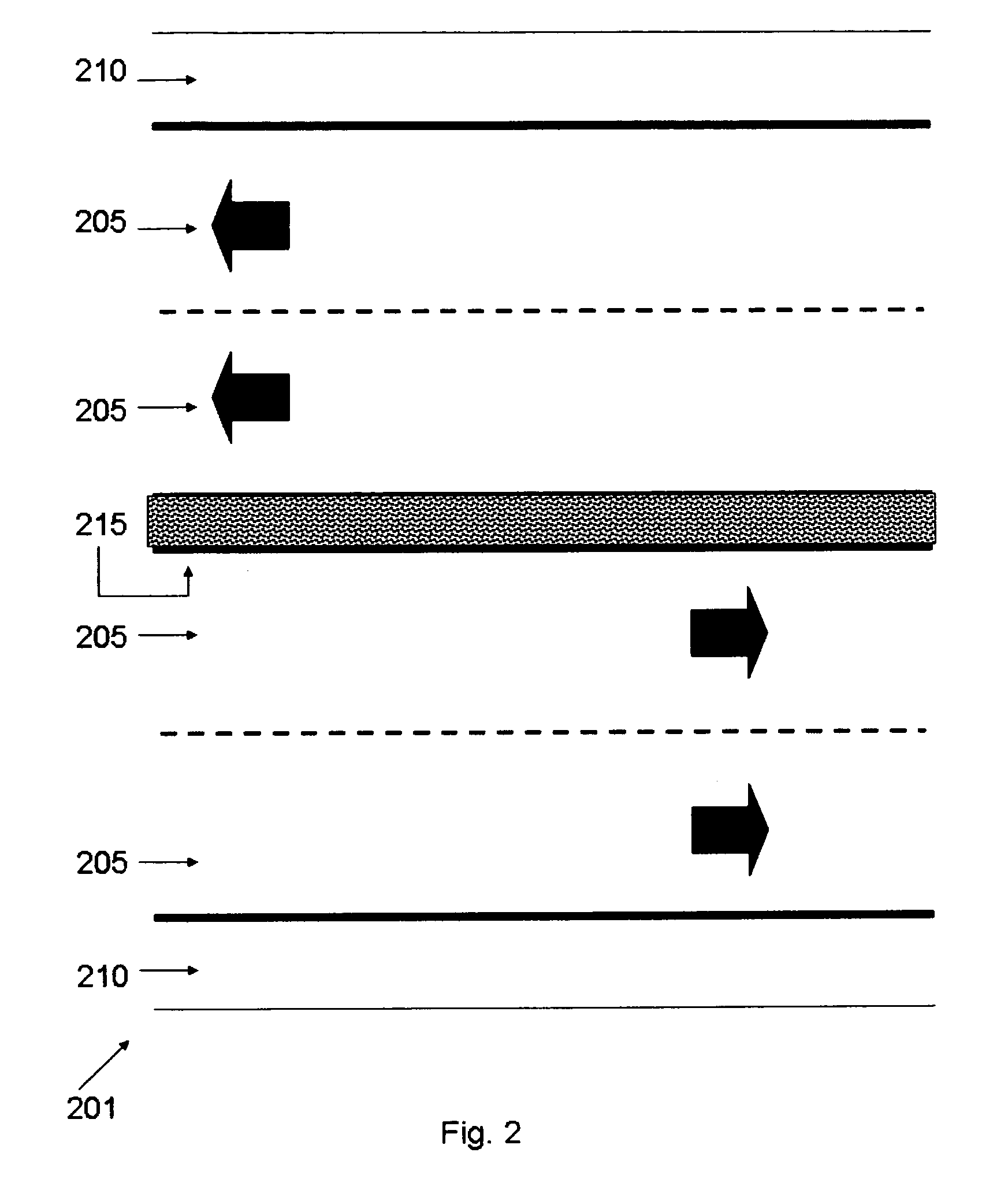
[0069]Reference is made to FIG. 2 which is a schematic aerial view of one embodiment of a road according to the present invention. A four-lane highway (201) has four lanes (205) heading in two directions. The highway (201) also has two shoulders (210) at the extreme sides of the highway (201). A center divider (215) rests between lanes (205) running in opposite directions.
[0070]One is referred to FIG. 3 which is a schematic cross-section of a lane of a road employing a board-based electrical energy production system (302). A board (303) is placed above a plurality of springs (304) and racks (309) located in a cavity (307) in a road (310), said springs (304) being connected at their base to a board compression modulation element (320). The cavity (307) in the road (310) may be created at the time a road is paved or it may be introduced retroactively into an existing road. The board (303) may be any material that can withstand the weights of potentially millions of cars travelling ove...
second embodiment
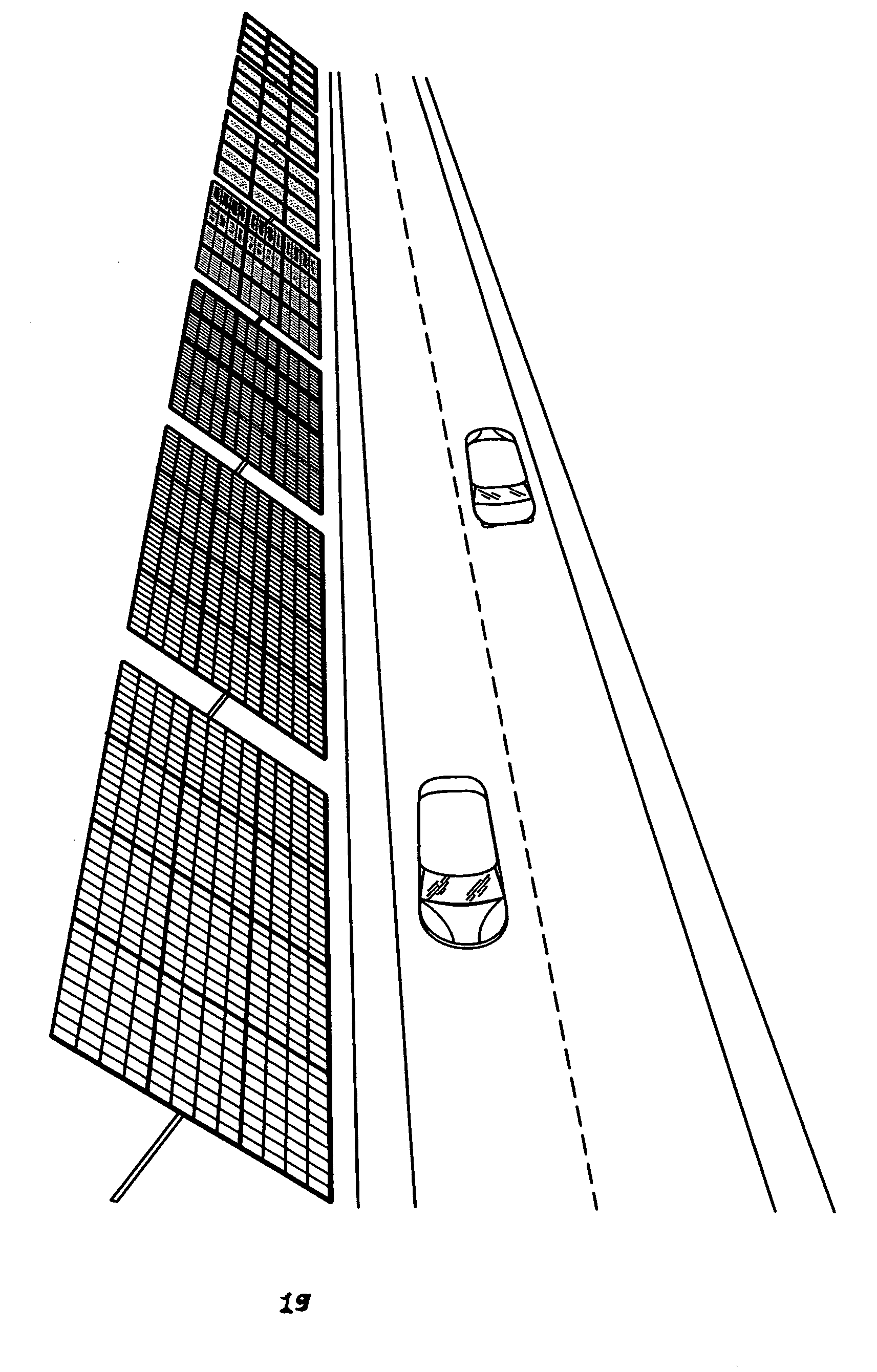
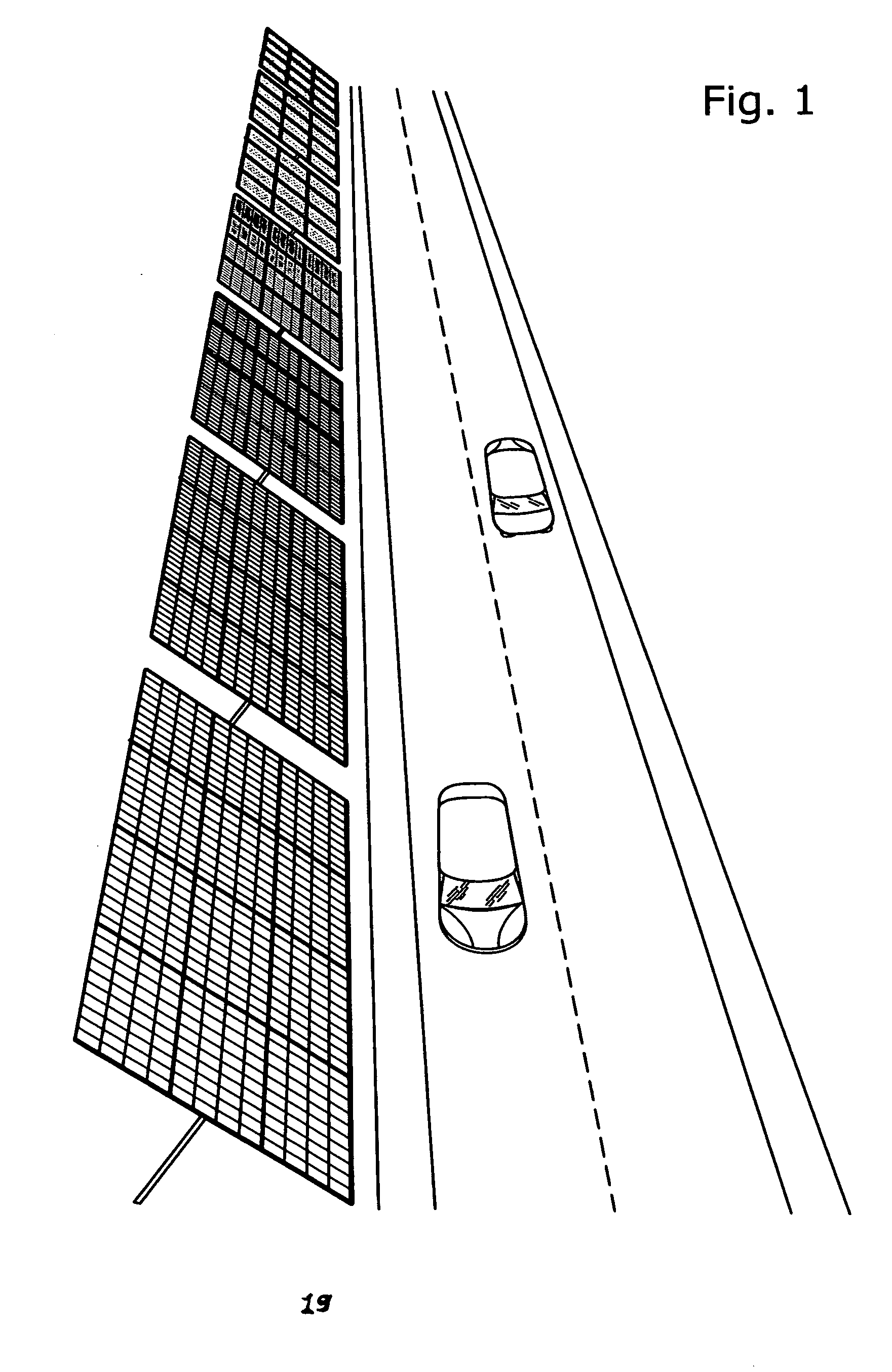
[0078]The present invention may be performed as described above, minimally with a road, a board, and a board-compression transduction element. While such a system would allow for generation of electricity from the passage of vehicles as described above and as shown in FIGS. 4-6, there are additional means of realizing clean electrical energy from paved roads. FIG. 9 shows photovoltaic cells (960) integrated into shoulders (910) of a four-lane divided highway (901). The photovoltaic cells (960) can be produced in any length and are made of a width to fit into the shoulder (910) of the highway (901) so as to never interfere with traffic in any lane (905) of the highway (901). Sunlight hits photovoltaic cells (960) and transfers generated electricity to a cable (930) that can transfer said electricity to a transmission line (940).
[0079]Reference is now made to FIG. 10 that shows the physical construction of a photovoltaic cell unit (1080) as used in the present invention. A ground ston...
PUM
 Abstract
Description
Claims
Application Information