Transmission Systems of Continuously Variable Transmission Ratio

a transmission ratio and transmission system technology, applied in mechanical equipment, transportation and packaging, gearing, etc., can solve the problems of transmission occupying a large space, relatively heavy and expensive transmission, and inacceptable in many automotive applications, and achieves more accurate axial positioning

Inactive Publication Date: 2009-08-06
NEXXTDRIVE LTD
View PDF2 Cites 4 Cited by
  • Summary
  • Abstract
  • Description
  • Claims
  • Application Information

AI Technical Summary

Benefits of technology

[0014]Alternatively, the or each stator portion may carry no electromagnetic coils and in this event they will constitute only a flux return member and the stator poles will be created by electromagnetic coils provided only on the other portion of the or each stator. In this event there will of course be no trailing electrical connections on the or each movable stator portion which need to be protected and unlimited rotation of the stator portion is therefore possible. In this event, the stator portion may be connected to the spigot portion by cooperating screw threads which perform many revolutions about the central axis. This will permit very much more accurate axial positioning of the stator portion with respect to the spigot portion.

Problems solved by technology

The necessity of providing three separate actuators makes the transmission relatively heavy and expensive and furthermore results in the transmission taking up a very considerable amount of space and this may be unacceptable in many automotive applications.
However, this is not always the case and in many transmission systems of the type referred to above the two motor / generators may be situated some considerable distance from one another.
Quite apart from the fact that these connections are susceptible to damage, they are also susceptible to fatigue stress due to their repeated movement and thus to failure in the medium to long term.

Method used


Image

  • Transmission Systems of Continuously Variable Transmission Ratio
  • Transmission Systems of Continuously Variable Transmission Ratio
  • Transmission Systems of Continuously Variable Transmission Ratio

Examples


Embodiment Construction

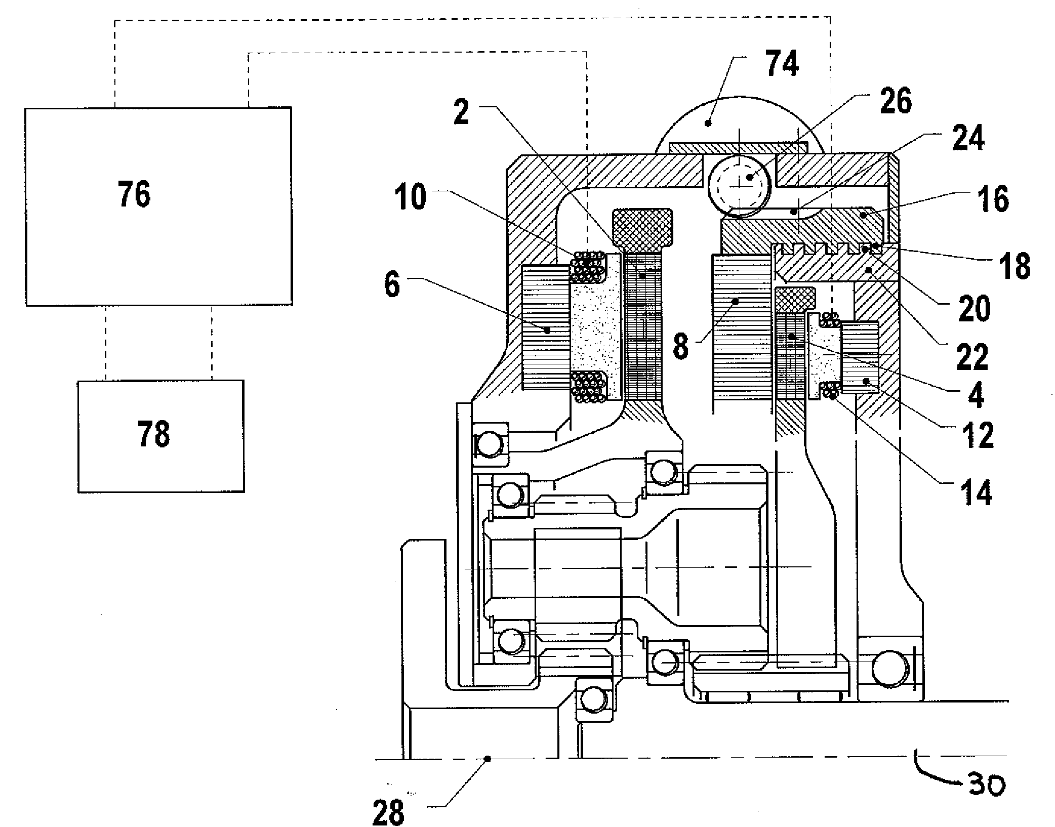
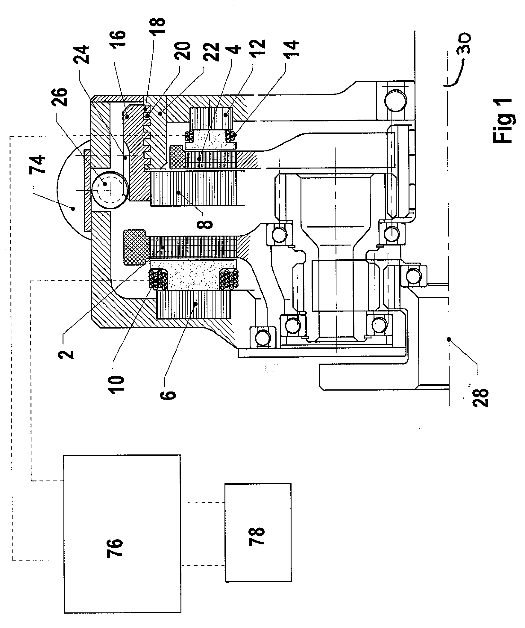
[0022]FIG. 1 shows a transmission system including an epicyclic gearset. The gearset is in this case of three branch type but since the gearset is known per se and may be generally the same as the gearsets disclosed in the prior document referred to above, both structurally and functionally, it will not be described in detail in the present application. However, two of the shafts 28, 30 of the gearset constitute an input and an output and two shafts are connected to respective rotors 2, 4 of permanent magnet type of two electric motor / generators. The motor / generator of which the rotor 2 forms part includes a stator consisting of two portions 6 and 8. The stator portion 6 is stationary and includes electromagnetic coils 10, which, in use, define the stator poles. The stator portion 8 carries no electromagnetic coils and therefore constitutes simply a flux return member. The stator portion 8 is made of laminated, grain orientated iron strip wound into a coil. The motor / generator of wh...


PUM


Abstract

A transmission system of continuously variable transmission ratio includes an input shaft, an output shaft, first and second electric motor/generators comprising first and second rotors and first and second stators, respectively, at least one of the motor/generators being of axial flux type, the first and second rotors being connected to rotate with respective shafts and the electrical connections of the first and second stators being connected together. A controller is arranged to control the flow of electrical power between the first and second stators. The stator of the said at least one motor/generator comprises two stator portions on opposite sides of the associated rotor, at least one of which is arranged to be movable in the axial direction. The said portion of the stator is rotatably secured to a spigot portion of the associated motor/generator extending in the axial direction by way of cooperating helical formations. An actuator is arranged to rotate one of the said portions of the stator and the spigot relative to the other, thereby moving the said portion of the stator in the axial direction with respect to the associated rotor.

Description

CROSS-REFERENCE TO RELATED APPLICATIONS[0001]This non-provisional application claims priority to British Patent Application No. 0802226.1 filed in Great Britain on Feb. 6, 2008, the entire contents of which are hereby incorporated by reference.BACKGROUND OF THE INVENTION[0002]The present invention relates to transmission systems of continuously variable transmission ratio of the type including an input shaft, an output shaft, first and second electric motor / generators comprising first and second rotors and first and second stators, respectively, at least one of the motor / generators being of axial flux type, the first and second rotors being connected to rotate with respective shafts and the electrical connections of the first and second stators being connected together, a controller arranged to control the flow of electrical power between the first and second stators, the stator of the said at least one motor / generator comprising two stator portions on opposite sides of the associat...

Claims


Application Information

Patent Timeline
Patent Type & Authority Applications(United States)
IPC IPC(8): H02K16/00
CPCB60K6/26B60K6/445Y02T10/6239H02K51/00H02K7/12Y02T10/62H02K7/116H02K16/00H02K2213/09F16H3/727
Inventor MOELLER, FRANK
Owner NEXXTDRIVE LTD
Why Eureka
Try Eureka