Integrated optical focusing/zooming system

Active Publication Date: 2007-10-18
BOLY MEDIA COMM SHENZHEN +1
View PDF14 Cites 3 Cited by
  • Summary
  • Abstract
  • Description
  • Claims
  • Application Information

AI Technical Summary

Benefits of technology

[0007]The present invention provides an integrated optical auto focus and zooming system, which has a simple structure and high transmission efficiency, and is capable of conveni

Problems solved by technology

In the current optical auto focus and zooming systems, a conventional motor is generally used to drive an optical lens (or lens set) through a transmission mechanism, such that the structure is complex.
As a result, the structure becomes even more complex, and the transmission efficiency of the system is reduced.
However, when an optical lens is driven by the torque output from an ultrasonic motor via the motor

Method used


Image

  • Integrated optical focusing/zooming system
  • Integrated optical focusing/zooming system
  • Integrated optical focusing/zooming system

Examples


first embodiment

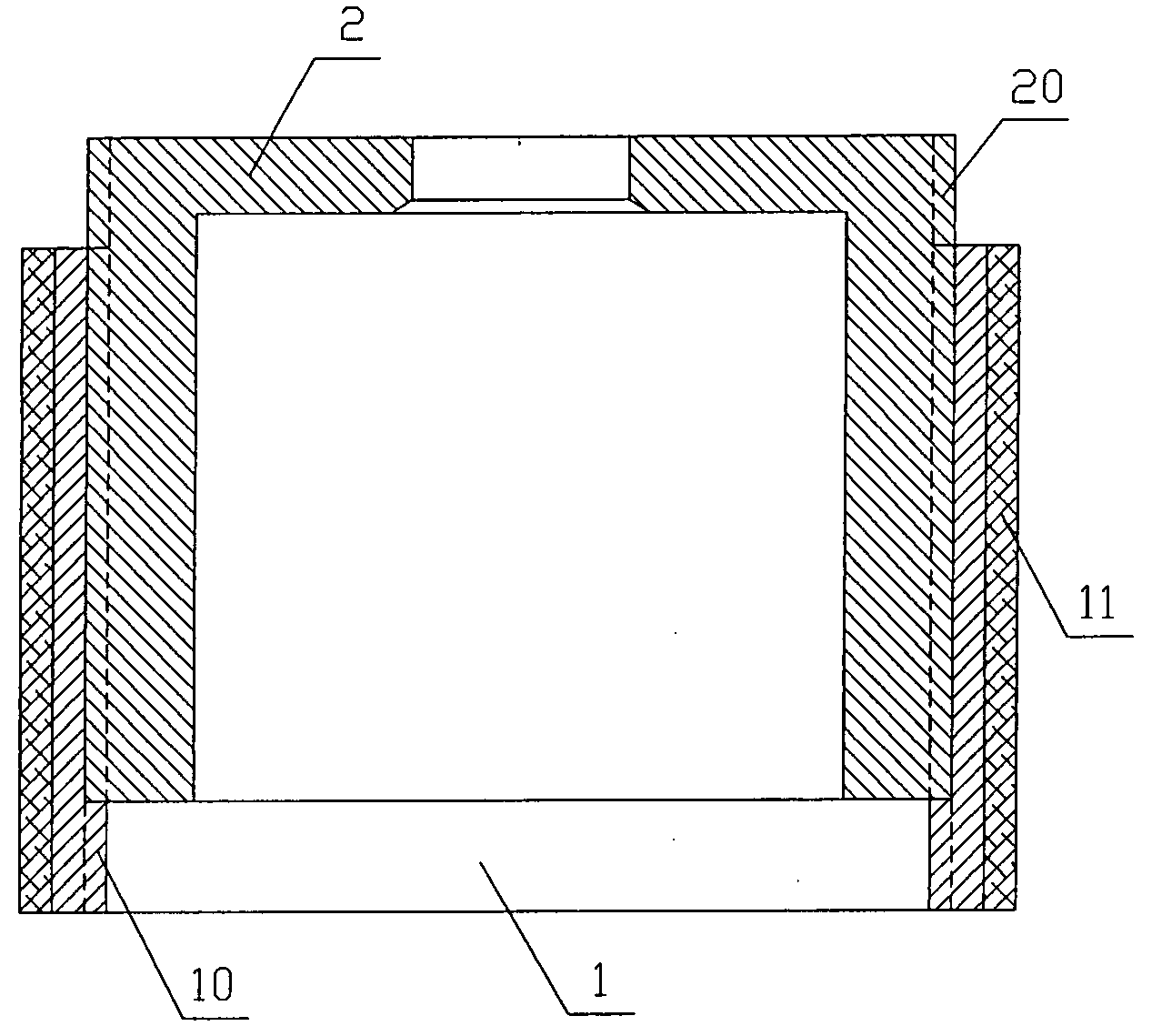
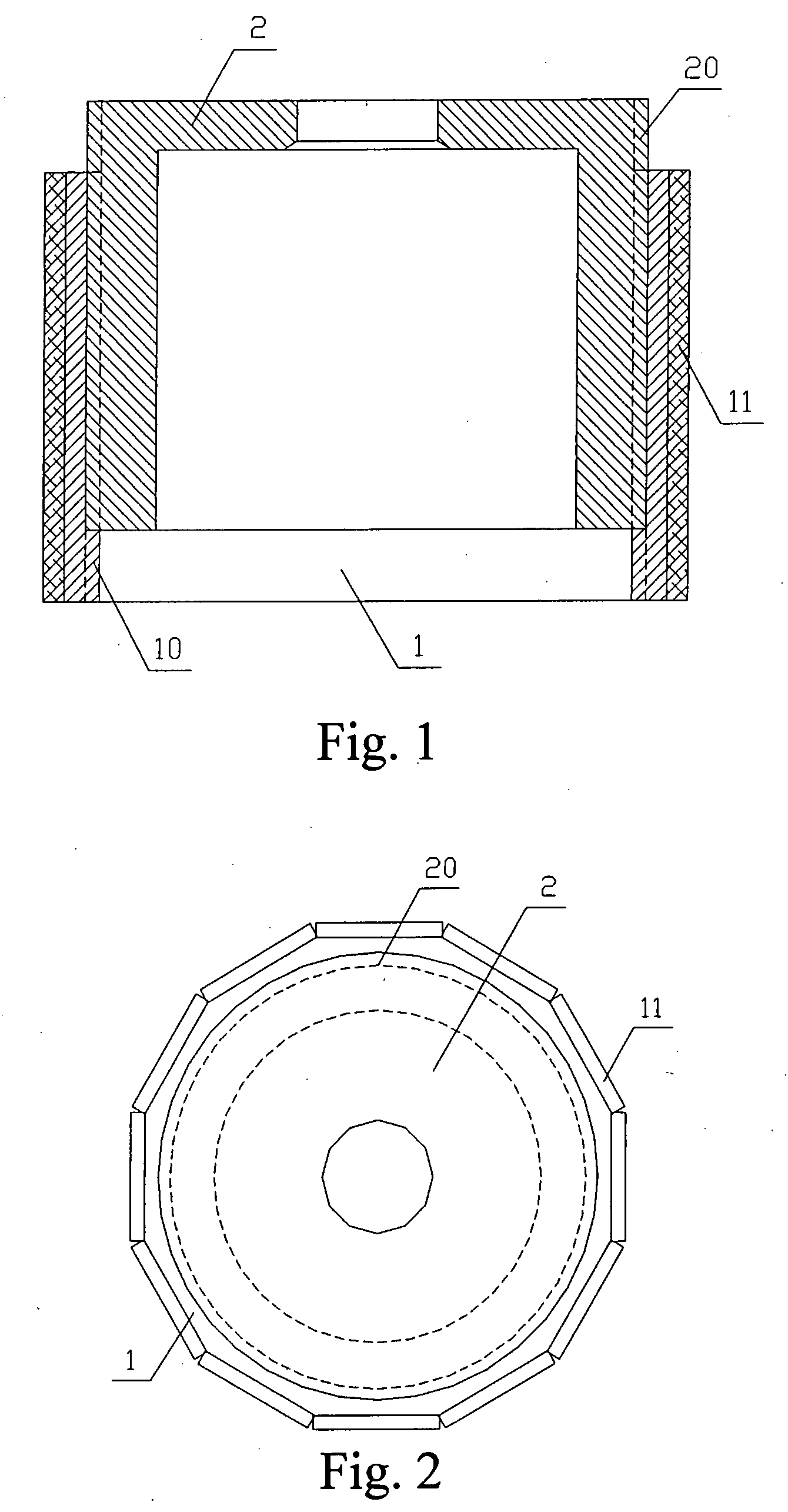
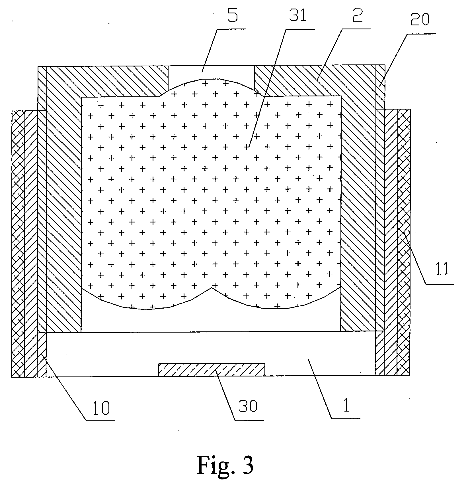
[0038]As shown in FIGS. 1 and 2, an integrated optical auto focus system includes a ring-shaped first casing 2 and a second casing 1 with a cylindrical center hole. The outer surface of the second casing 1 is a regular dodecahedron, twelve piezoelectric elements 11 (the piezoelectric elements 11 may be piezoelectric ceramics, and may be flake-shaped, arc-shaped, column-shaped, or various polyhedron-shaped, overall ring-shaped, cone-shaped, or piecewise circular piezoelectric elements) are respectively adhered on to each of the twelve surface segments of the regular dodecahedron. The second casing 1 is screwed into the first casing 2 through the cylindrical center hole, and the second casing 1 and the first casing 2 are connected through threads at positions where they are in contact. The internal threads 10 are fabricated on the inner wall of the cylindrical center hole of the second casing 1, and the corresponding external threads 20 are fabricated on the outer surface of the first...

second embodiment

[0041]Another integrated optical auto focus and zooming system is shown in FIG. 4. The main difference between FIG. 4 of this embodiment and FIG. 3 of the first embodiment lies in that, in this embodiment of FIG. 4, the second optical lens 32 is placed in the second casing 1, so as to achieve larger focus adjustment range or to reduce the weight of moving parts. As a common practice, an infrared cut glass 50 is placed between the second optical lens 32 and the image sensor 30, so as to prevent infrared light from passing there through. The structures of the other parts in FIG. 4 are the same as or similar to that of FIG. 3 in the first embodiment, which thus will not be described herein.

third embodiment

[0042]As shown in FIG. 5, a third integrated optical auto focus and zooming system includes a ring-shaped first casing 2 and a second casing 1 having a cylindrical center hole. A second optical lens 32 and a third optical lens 33 are placed in the second casing 1. The optical lens 31 is placed in the first casing 2, and the first casing 2 is embedded between the second optical lens 32 and the third optical lens 33 in the second casing 1 and is wrapped by second casing 1 through screw matching. The external threads 20 placed on the cylindrical surface of the first casing 2 are screwed and connected with the internal threads 10 on the inner wall of the second casing 1. The outer side surface of the second casing 1 is a regular dodecahedron, and twelve piezoelectric elements 11 are respectively adhered on to each of the twelve surface segments of the regular dodecahedron. The image sensor 30 is placed at the center position of one end in the second casing 1, an aperture 5 is opened at ...


PUM


Abstract

An integrated optical auto focus and zooming system is provided, which includes a first optical lens, a first hollow casing, a second hollow casing, a plurality of piezoelectric elements. The first optical lens is placed in the first hollow casing, the first hollow casing and the second hollow casing are screwed with each other, and the plurality of piezoelectric elements are attached either on the first hollow casing or the second hollow casing. Upon the excitation of mechanical vibrations by the plurality of piezoelectric elements, a traveling wave is generated on the attached casing, so as to drive the other casing to rotate and then to move axially. Additional lens groups and casings can be added in the same way so to achieve multiple relative motions between lens groups and image sensor, and thus achieving the objectives of focusing and zooming. The present invention integrates the motor into the lens and hence eliminates the transmission mechanism, leading to simple structure, high efficiency, and multiple advantages in size, cost, and efficiency, etc., and thus can be very useful.

Description

BACKGROUND OF THE INVENTION[0001]1. Field of the Invention[0002]The present invention relates to optics, more particularly, to an integrated optical auto focus and zooming system.[0003]2. Description of Related Art[0004]In the current optical auto focus and zooming systems, a conventional motor is generally used to drive an optical lens (or lens set) through a transmission mechanism, such that the structure is complex. In addition, since conventional motors have a relatively high rotating speed, mostly, a speed-restraining mechanism is required additionally. As a result, the structure becomes even more complex, and the transmission efficiency of the system is reduced.[0005]Lately ultrasonic motors (e.g., U.S. Pat. No. 6,940,209) that utilize the reverse piezoelectric effect of piezoelectric materials and a driving mechanism formed by a specific design are adopted, which consist of only functional members such as a stator and a rotor with piezoelectric elements fixed on the stator. S...

Claims


Application Information

Patent Timeline
IPC IPC(8): G03B17/00G02B7/02G03B30/00
CPCG02B7/021G03B3/10G02B7/102G02B7/023
Inventor HU, XIAOPINGTIAN, BINLI, YIZHOU, TIEYINGLU, CUNYUECHEN, YU
Owner BOLY MEDIA COMM SHENZHEN
Why Eureka
Try Eureka