Rack device and incubator having the same

a rack and incubator technology, applied in the field of rack devices, can solve problems such as the accident of receiver separation, and achieve the effects of stable and safe culturing operation, easy addition of the receiver, and arbitrarily changing the rack heigh

Inactive Publication Date: 2009-08-06
PANASONIC HEALTHCARE HLDG CO LTD
View PDF12 Cites 15 Cited by
  • Summary
  • Abstract
  • Description
  • Claims
  • Application Information

AI Technical Summary

Benefits of technology

[0010]According to the invention, a rack device having a receiver mounted between a pair of rack posts to hold a rack on the receiver includes a pair of engaging hooks which are formed in the receiver and a plurality of engaging holes which are formed in both the rack posts and with which both the engaging hooks of the receiver disengageably engage, respectively, and the rack posts are configured to be able to change an interval therebetween and select a first state in which the engaging hooks can be disengaged from the engaging holes and a second state in which a movement of the receiver is restricted while the engaging hooks are kept to engage with the engaging holes by changing the interval between the rack posts. Accordingly, when a height of the rack is changed, the state of the rack posts is adjusted to the first state to disengage the engaging hooks of the receiver from the engaging holes of the rack posts and change a position of the receiver with respect to the rack posts. In this manner, the height of the rack can be arbitrarily changed.
[0011]Further, when the engaging hooks of the receiver are engaged with any engaging hole of the rack posts and the position is decided in this state, only by changing the interval between the rack posts and setting the second state, the movement of the receiver is restricted while the engaging hooks of the receive

Problems solved by technology

Accordingly, when the rack is removed from the culturing chamber, the engaging hooks are disengaged from the engaging holes just by, for

Method used


Image

  • Rack device and incubator having the same
  • Rack device and incubator having the same
  • Rack device and incubator having the same

Examples


Embodiment Construction

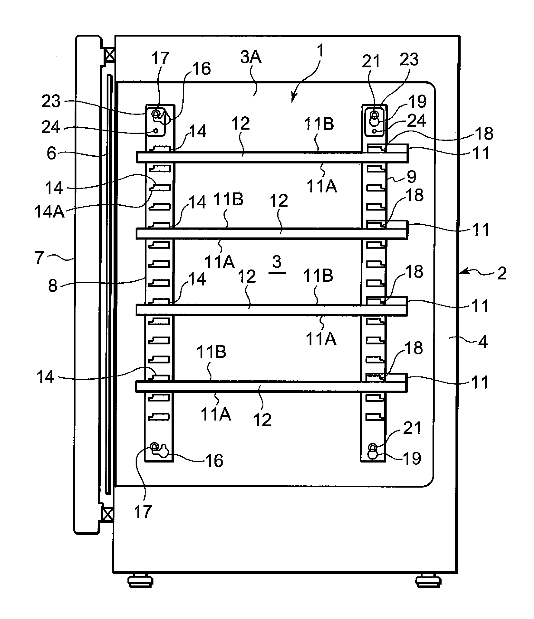
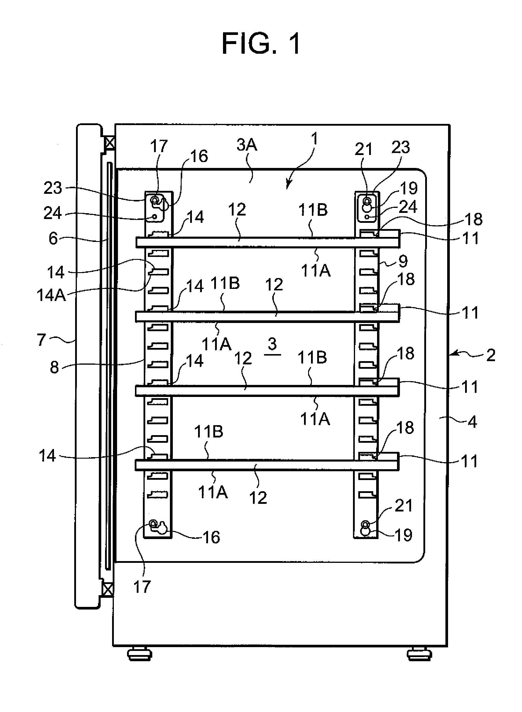
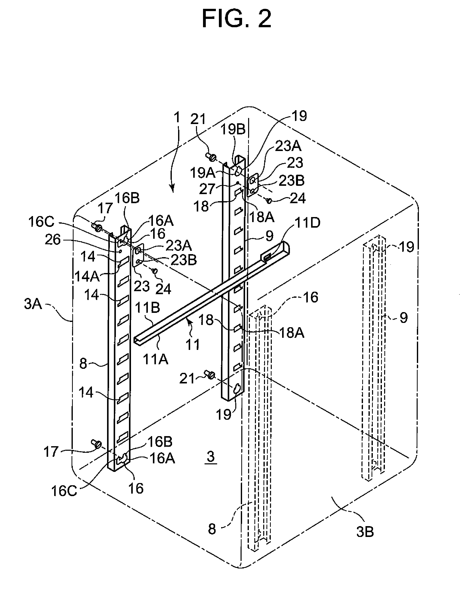
[0024]Next, an embodiment of the invention will be described based on the drawings. FIG. 1 is a schematic longitudinal sectional side view of an incubator 2 according to the embodiment to which a rack device 1 according to the invention is applied, FIG. 2 is a perspective view of the inside of a culturing chamber 3 of the incubator 2 from which the rack device 1 according to the invention is disassembled, and FIG. 3 is an enlarged view illustrating the rack device 1 according to the invention.

[0025]The incubator 2 according to the embodiment to which the invention is applied has a heat insulating container box 4, the culturing chamber 3 constituted in the heat insulating container box 4 and having an opened front surface, and openable interior and exterior doors 6 and 7 for closing the front surface opening of the culturing chamber 3. In the culturing chamber 3, a predetermined temperature (about +37° C.) and humidity (high humidity of 90% or more) suitable for culturing cultures su...


PUM


Abstract

A rack device is provided in which a receiver can be prevented from being separated off from a rack post and an incubator having the rack device is also provided. A rack device 1 in which a receiver 11 is mounted between a pair of rack posts 8 and 9 to hold a rack on the receiver 11 includes a pair of engaging hooks 11C and 11D which are formed in the receiver and a plurality of engaging holes 14 and 18 which are formed in both the rack posts and in which both of the engaging hooks of the receiver disengageably engage, respectively. The rack posts are configured to be able to change an interval therebetween and select a first state in which the engaging hooks can be disengaged from the engaging holes and a second state in which the movement of the receiver is restricted while the engaging hooks be kept to engage in the engaging holes by changing the interval between the rack posts.

Description

BACKGROUND OF THE INVENTION[0001]The present invention relates to a rack device having a receiver mounted between a pair of rack posts to hold and support a rack on the receiver, and an incubator including the rack device.[0002]Incubators for culturing cells or microbes (cultures) form a temperature / humidity / gas environment suitable for culturing the cultures in a culturing chamber. In the culturing chamber opened at the front, a rack device is provided to place a plurality of containers (Petri dishes and the like) accommodating the cultures (for example, see Japanese Patent Application Laid-Open No. 2000-166536).[0003]In this case, the rack device includes pairs of front and rear rack posts which are fixed to right and left side walls of the culturing chamber, respectively, a pair of right and left receivers which are mounted between the front and rear rack posts on both of the side walls, respectively, and a rack which is held between both of the receivers. In this case, the recei...

Claims


Application Information

Patent Timeline
IPC IPC(8): B01L7/00A47B81/00
CPCA47B57/40C12M41/14C12M23/48A47B88/044A47B88/43A47B57/32C12M1/36C12M3/00
Inventor OSAWA, SHINJIBUSUJIMA, HIROKI
Owner PANASONIC HEALTHCARE HLDG CO LTD
Why Eureka
Try Eureka