Liquid jet apparatus and printing apparatus

a technology of liquid jet and printing apparatus, which is applied in the direction of printing and other printing apparatus, etc., can solve the problems of large loss, increased electric potential difference between the terminals of the coil employed in the low-pass filter, and large loss produced

Inactive Publication Date: 2009-08-06
SEIKO EPSON CORP
View PDF2 Cites 5 Cited by
  • Summary
  • Abstract
  • Description
  • Claims
  • Application Information

AI Technical Summary

Benefits of technology

[0006]An object of the invention is to provide a liquid jet apparatus in which when a digital power amplifier is used to amplify a power, the order of a low pass filter can be decreased and a high-definition drive signal can be produced.

Problems solved by technology

If an analog power amplifier including push-pull-connected transistors that are linearly driven is used to amplify the power of the drive signal, a large loss is produced and a large heat sink for heat radiation is needed.
In this case, a electric potential difference between the terminals of a coil employed in the low pass filter increases, and a loss derived from hysteresis increases.

Method used


Image

  • Liquid jet apparatus and printing apparatus
  • Liquid jet apparatus and printing apparatus
  • Liquid jet apparatus and printing apparatus

Examples


Embodiment Construction

[0036]Next, the first embodiment of a liquid jet type printing apparatus to which a liquid jet apparatus of the invention is adapted will be described below.

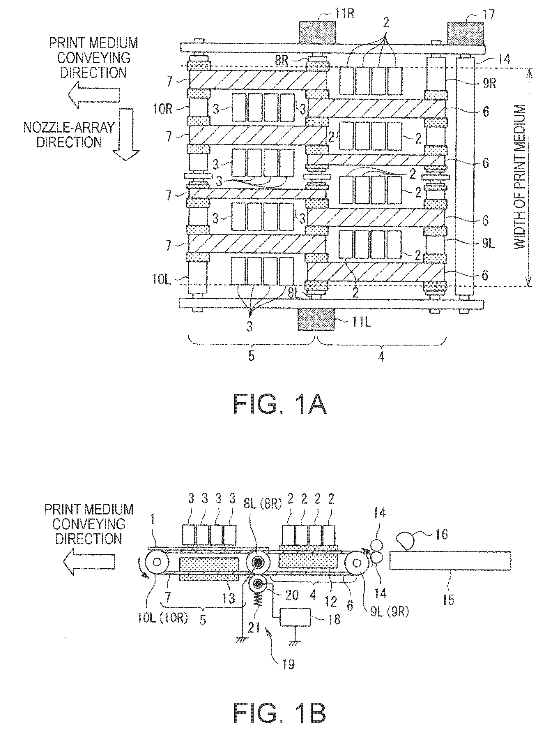
[0037]FIG. 1A and FIG. 1B are schematic construction diagrams of the liquid jet type printing apparatus of the first embodiment. FIG. 1A is a plan view, and FIG. 1B is a front view. In FIG. 1A and FIG. 1B, a print medium 1 is conveyed in an arrow direction from right to left in the drawing, and printing is performed in a printing field in the middle of the conveyance. Thus, the liquid jet type printing apparatus may be referred to as a line head type printing apparatus.

[0038]Reference numeral 2 denotes a first liquid jet head disposed on the upstream side of a conveying direction in which the print medium 1 is conveyed. Reference numeral 3 denotes a second liquid jet head disposed on the downstream side thereof. A first conveying section 4 that conveys the print medium 1 is disposed below the first liquid jet heads 2, and a seco...


PUM


Abstract

A liquid jet apparatus of the invention includes a drive waveform generator that generates a drive waveform signal, a modulator that pulse-modulates the drive waveform signal so as to produce a modulated signal, a digital power amplification circuit that amplifies the power of the modulated signal so as to produce an amplified digital signal, and a low pass filter that smoothes the amplified digital signal so as to produce a drive signal. The digital power amplification circuit includes multiple stages of digital power amplifiers each including a pair of switching elements that are push-pull-connected. The amplified digital signal is a multi-value signal that reaches a larger number of steps of electric potentials than the number of digital power amplifiers.

Description

BACKGROUND[0001]1. Technical Field[0002]The present invention relates to a liquid jet apparatus that jets a little liquid through multiple nozzles so as to form a minute particle (dot) on a medium, and thus forms a predetermined letter or image, and a printing apparatus to which the liquid jet apparatus is adapted.[0003]2. Related Art[0004]In liquid jet type printing apparatuses to which a liquid jet apparatus is adapted, a drive signal which has the power thereof amplified by a power amplification circuit is applied to actuators such as piezoelectric elements so that liquid will be jetted out through nozzles. If an analog power amplifier including push-pull-connected transistors that are linearly driven is used to amplify the power of the drive signal, a large loss is produced and a large heat sink for heat radiation is needed. According to JP-A-2005-329710, a digital power amplifier is used to amplify the power of the drive signal, whereby the loss is minimized and the necessity o...

Claims


Application Information

Patent Timeline
Patent Type & Authority Applications(United States)
IPC IPC(8): B41J29/38
CPCB41J2/04541B41J2/0455B41J2/04591B41J2/04588B41J2/04581
Inventor OSHIMA, ATSUSHI
Owner SEIKO EPSON CORP
Why Eureka
Try Eureka