MIM capacitor integration

a technology of metal-insulator metal and capacitor, which is applied in the manufacture of integrated circuits including metal-insulator metal capacitors, etc., can solve the problems of consideration of process constraints

Active Publication Date: 2009-08-13
III HLDG 12 LLC
View PDF13 Cites 51 Cited by
  • Summary
  • Abstract
  • Description
  • Claims
  • Application Information

AI Technical Summary

Problems solved by technology

The need to satisfy all of these requirements in a common etching process places considerable constraints on that process, notably in terms of finding an etching species that will have a suitable pattern of selectivities.

Method used


Image

  • MIM capacitor integration
  • MIM capacitor integration
  • MIM capacitor integration

Examples


Embodiment Construction

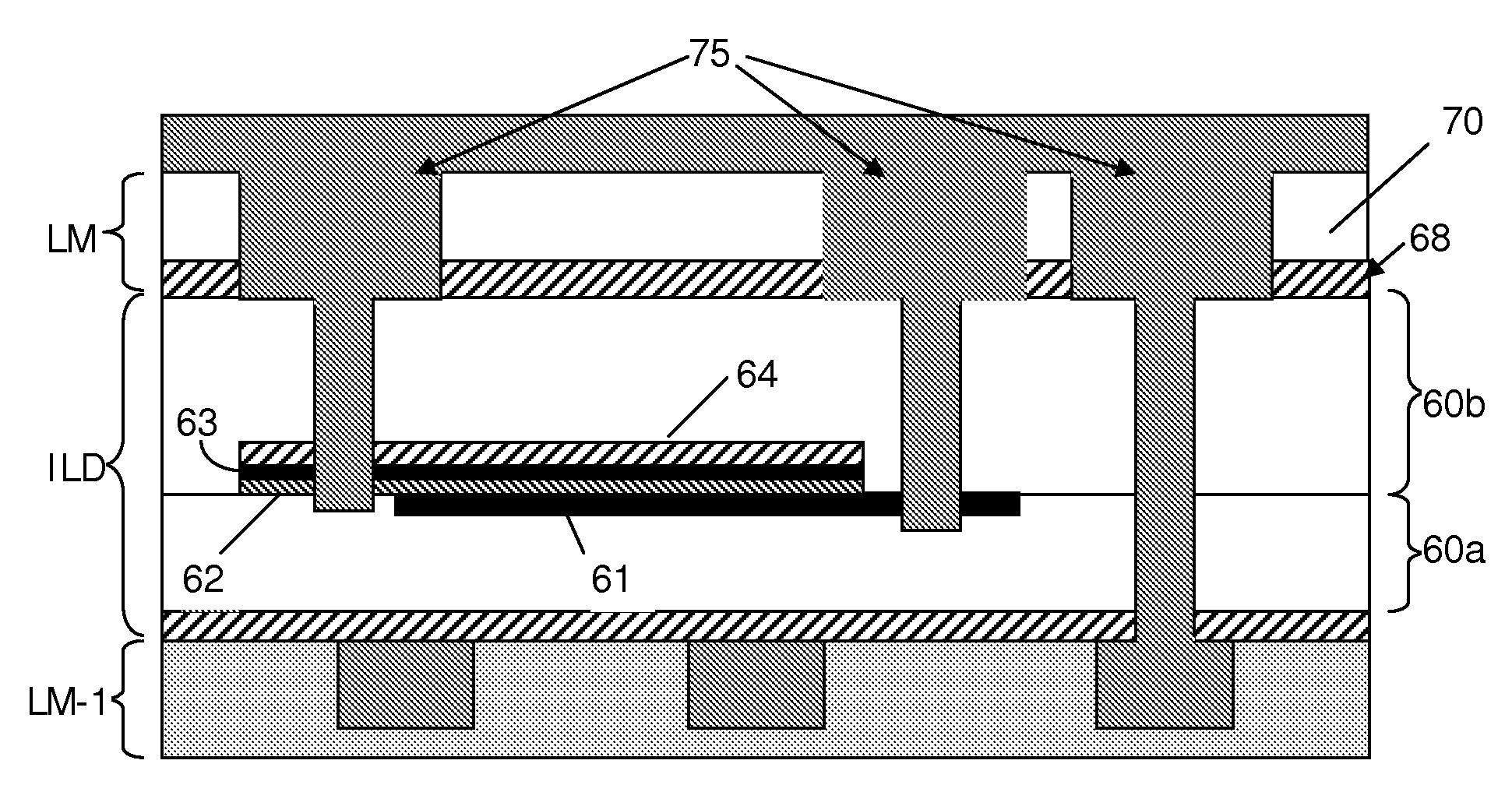
[0020]A first embodiment of the present invention will now be described with reference to FIGS. 3 and 4. FIG. 3 illustrates the architecture of the MIM capacitor according to the first embodiment and FIGS. 4A to 4H illustrate stages in the manufacture of the architecture of FIG. 3.

[0021]The first embodiment will be described in the context of a fabrication process in which a MIM capacitor is formed within an interlayer dielectric layer between the LM and LM-1 metallization layers. However, it is to be understood that the same structure and techniques can be used regardless of the metallization layers between which the MIM capacitor is formed (i.e. between M1 and M2, between M2 and M3, etc.).

[0022]As illustrated in FIG. 3, according to the first embodiment of the invention the LM-1 metallization layer consists of a dielectric 50, such as a low-k material (e.g. Black Diamond I made by Applied Materials Inc. of California, USA), an ultra-low-k (ULK) material (e.g. Black Diamond II, a p...


PUM


Abstract

An integrated metal-insulator-metal capacitor is formed so that there is an extension portion of its top plate that does not face any portion of the bottom plate, and an extension portion of its bottom plate that does not face any portion of the top plate. Vias connecting the MIM capacitor plates to conductors in an overlying metallization layer are formed so as to contact the extension portions of the top and bottom plates. Etching of the via holes is simplified because it is permissible for the via holes to punch through the extension portions of the capacitor plates. The bottom plate of the MIM capacitor is inlaid. The top plate of the MIM capacitor may be inlaid.

Description

FIELD OF THE INVENTION[0001]The present invention relates to integrated circuit manufacture and, more particularly, to the manufacture of integrated circuits including metal-insulator-metal (MIM) capacitors.BACKGROUND OF THE INVENTION[0002]During the manufacture of integrated circuit devices, notably RF or analog-mixed signal (AMS) integrated circuit devices, it is often desired to include capacitors in the circuits. Increasingly this is being achieved using MIM capacitors, especially high dielectric constant (high-k) MIM capacitors.[0003]A number of different architectures have been proposed for integrating MIM capacitors during semiconductor manufacturing processes. In some of these architectures a MIM capacitor is formed by providing a lower plate, a dielectric layer and an upper plate stacked up within an interlayer dielectric layer located between two metal (interconnect) layers. For example, such a MIM capacitor may be provided in the interlayer dielectric between the penultim...

Claims


Application Information

Patent Timeline
Patent Type & Authority Applications(United States)
IPC IPC(8): H01L27/06H01L21/82
CPCH01L28/40H01L21/76816
Inventor SMITH, BRAD
Owner III HLDG 12 LLC
Why Eureka
Try Eureka