Illumination unit with current interrupter component

a current interrupter and illumination unit technology, applied in lighting and heating apparatus, electrical variable regulation, light fastenings, etc., can solve problems such as life and property, danger even more acute, and typical current-limiting measures such as current-limiting diodes, and achieve the effect of facilitating illumination

Inactive Publication Date: 2009-08-13
AMDOR
View PDF9 Cites 32 Cited by
  • Summary
  • Abstract
  • Description
  • Claims
  • Application Information

AI Technical Summary

Problems solved by technology

If there is a malfunction in one of the lighting systems, it will tend to draw the maximum current from the battery and, unless otherwise protected, the smaller LED-based compartment illumination units, which are designed for lower amperage, can overheat and cause a fire.
Because the lighting systems, including the LED-based compartment illumination units, can be connected in series, typical current-limiting measures, such as current-limiting diodes, are generally unsuitable.
Moreover, while in prior art embodiments of LED-based illuminations units, fuses have been included in the power supply cords for those lighting units, these fuses are often inadvertently removed when the power supply cords are trimmed, or cut off altogether, as part of the installation process, thereby removing the fuse from the electrical circuit of the illumination unit.
While there is obviously a danger to life and property associated with the risk of one of the smaller LED-based compartment illumination units catching fire due to a lighting system malfunction, where the LED-based compartment illumination unit is located on a firefighting vehicle, the danger is even more acute because the fire can hamper the operations of the firefighters at a time when lives hang in the balance.
In addition, even if no-one is injured as a result of such a fire and property damage is limited, there is still the ignominy of having a firefighting vehicle catch fire.

Method used


Image

  • Illumination unit with current interrupter component
  • Illumination unit with current interrupter component
  • Illumination unit with current interrupter component

Examples


Embodiment Construction

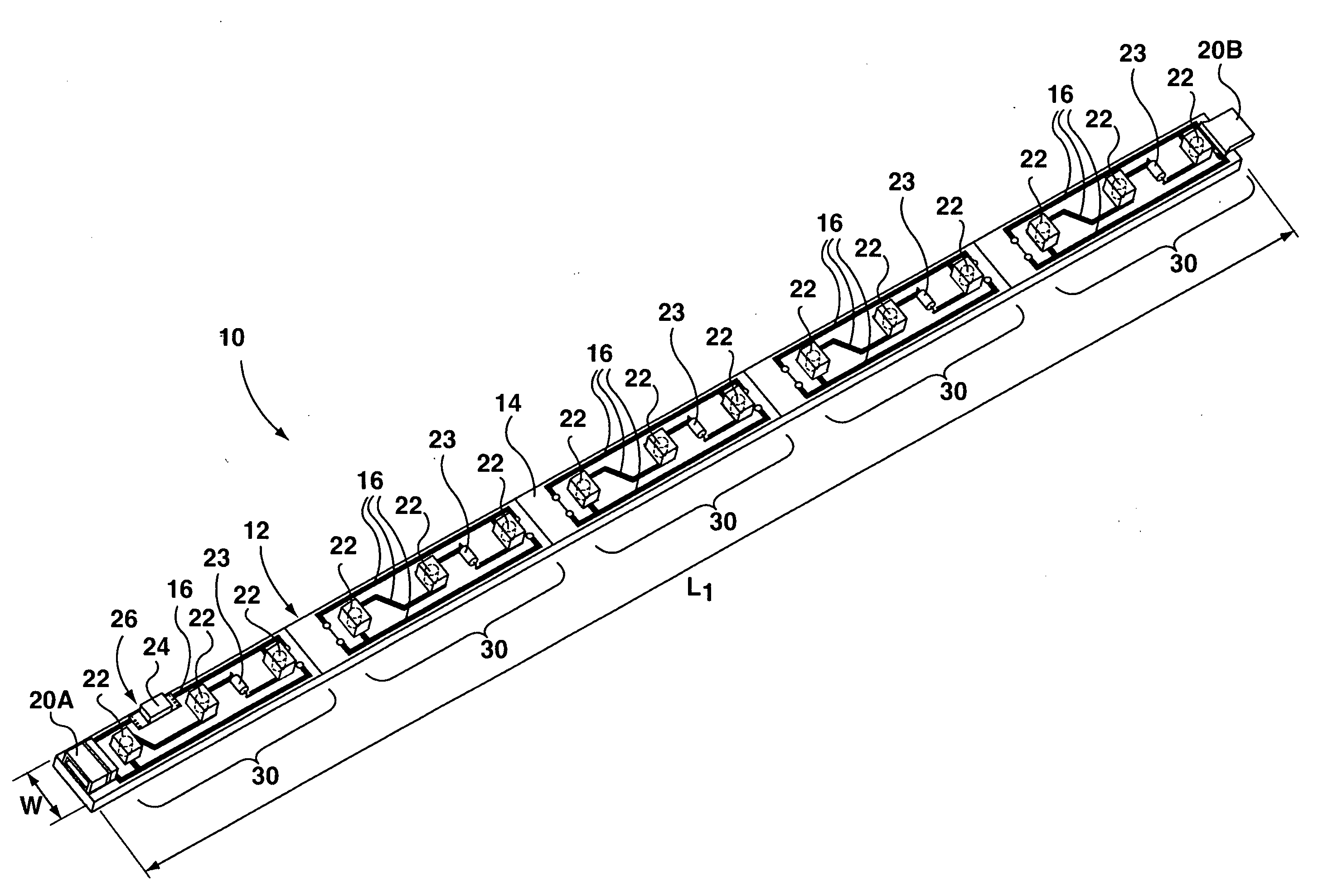
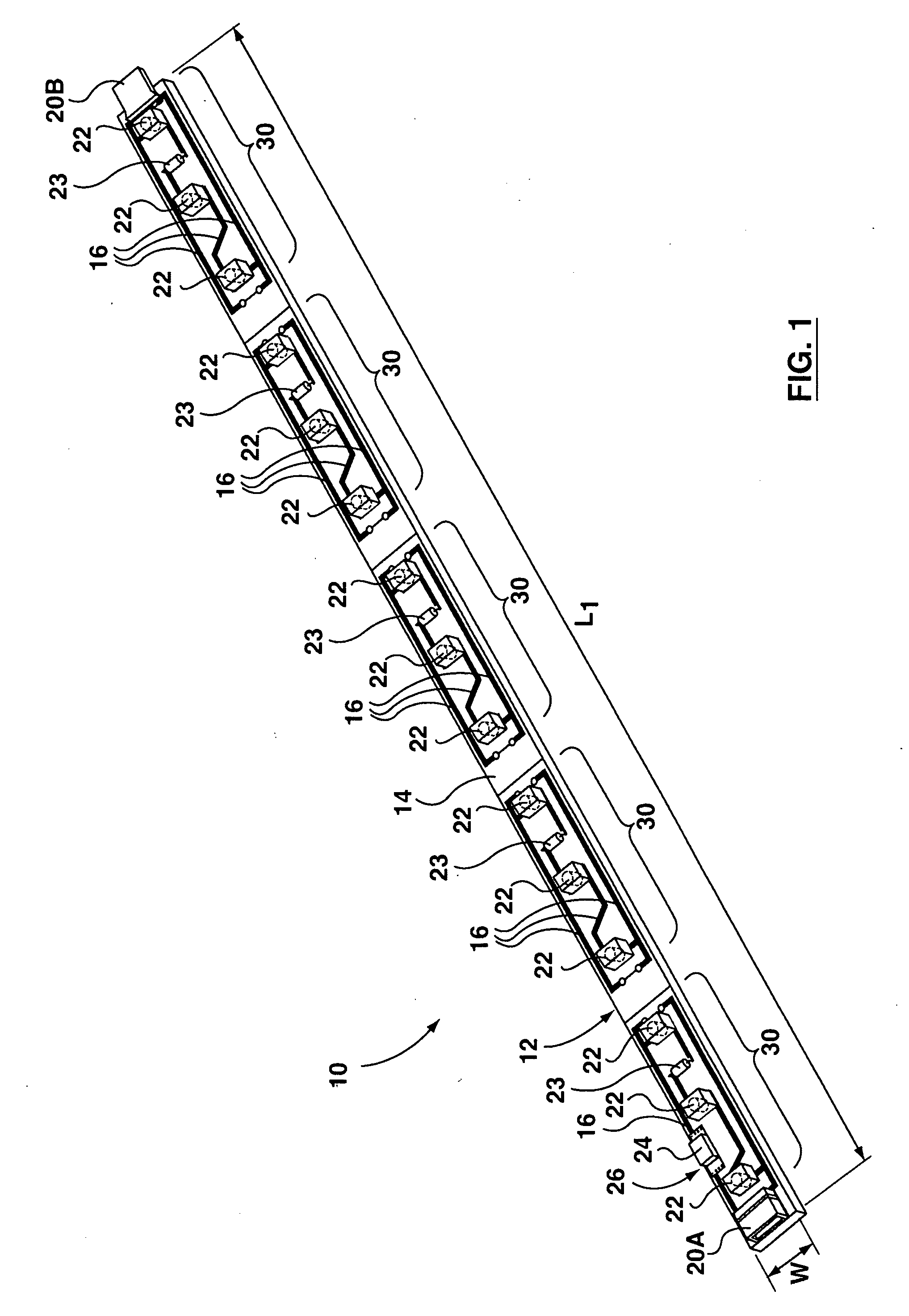
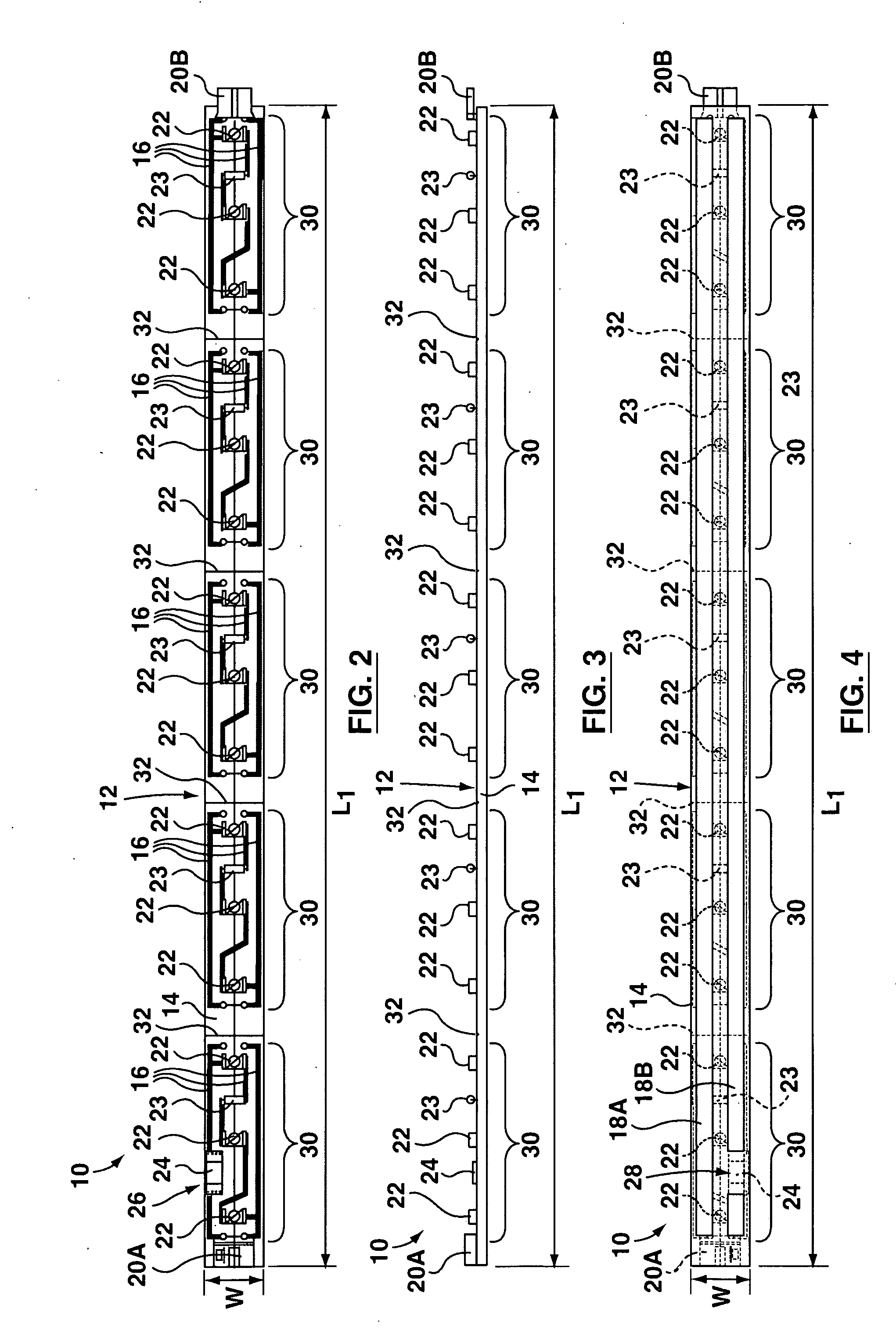
[0042]With reference now to FIGS. 1 to 4, an exemplary embodiment of a light-carrying member for an illumination unit in accordance with an aspect of the present invention is indicated generally at 10. While illumination units according to aspects of the present invention may be used in any suitable environment, the exemplary illumination units shown and described herein are particularly well suited for illuminating storage compartments on vehicles, such as firefighting vehicles, transport trucks, and the like. An illumination unit according to an aspect of the present invention may consist simply of a single light-carrying member, such as the light-carrying member 10, or may consist of two or more light-carrying members coupled together. In addition, an illumination unit according to an aspect of the present invention may comprise a combination of one or more such light-carrying members with other components, such a cover member or other exterior envelope, as described below.

[0043]...


PUM


Abstract

An illumination unit comprises at least one electrical coupling element for receiving electrical current from a current source and coupling the illumination unit into an electrical system, a light-carrying member, and an electrical circuit adapted for electrical coupling to the current source via the electrical coupling element. The electrical circuit comprises at least one light-emitting diode carried by the light-carrying member, and a current interrupter component interposed in the electrical circuit. The current interrupter component permits current flow within the electrical circuit when a parameter of the electrical circuit remains below a predetermined value, and opens the electrical circuit in response to the parameter of the electrical circuit exceeding the predetermined value. The current interrupter component may be carried by the light-carrying member, or may be contained within an exterior envelope at least partially surrounding the electrical circuit.

Description

CROSS-REFERENCE TO RELATED APPLICATIONS[0001]This application is a continuation-in-part of U.S. patent application Ser. No. 11 / 798,648 filed on May 16, 2007.FIELD OF INVENTION[0002]The present invention relates to illumination units, and more particularly to safety arrangements for illumination units.BACKGROUND OF THE INVENTION[0003]It is common for transport vehicles, such as transport trucks, to have illumination units comprising at least one LED, and typically a plurality of LEDs, for use in illuminating storage compartments (including the main transport compartment) on those vehicles. Typically, a vehicle's lighting systems, including the headlights and the LED-based compartment illumination units, are powered by the vehicle's electrical system, possibly in series, and a circuit breaker is employed. If there is a malfunction in one of the lighting systems, it will tend to draw the maximum current from the battery and, unless otherwise protected, the smaller LED-based compartment...

Claims


Application Information

Patent Timeline
Patent Type & Authority Applications(United States)
IPC IPC(8): H05B37/00F21V33/00B60Q1/00
CPCA47B97/00F21V17/02B60Q1/32B60Q3/06F21S4/008F21V19/0045F21V19/02F21V23/04F21V23/06F21V33/0012F21Y2101/02F21V25/10F21V31/005F21V17/005B60Q1/2696B60Q3/30F21S4/28F21Y2115/10
Inventor WHITEHOUSE, DOUGLAS BRUCETURNER, KENNETH VICTORMCNABB, ORAN WILLIAM
Owner AMDOR
Why Eureka
Try Eureka