

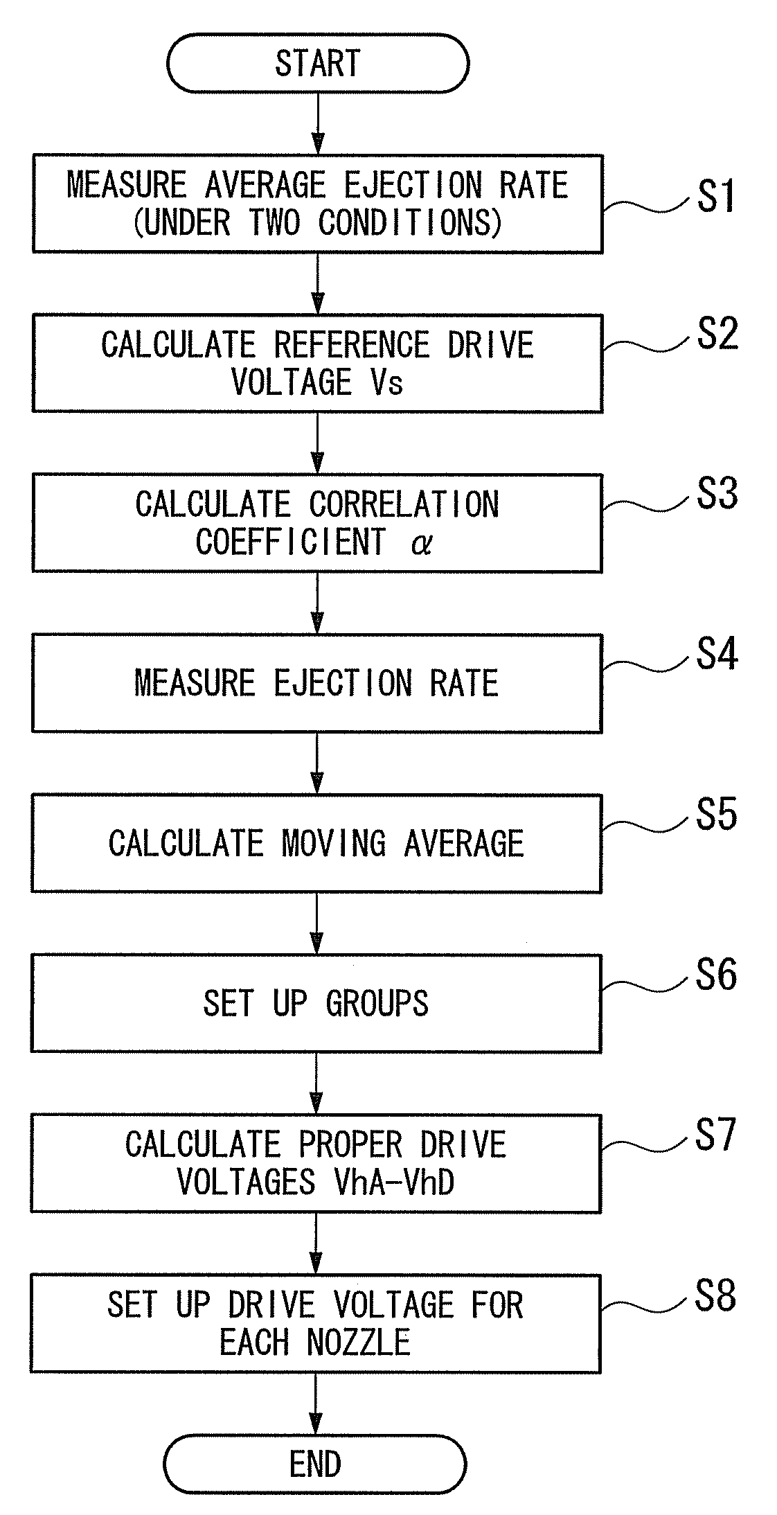
Method for setting up drive signal
a technology of drive signal and signal, which is applied in the direction of printing, inking apparatus, other printing apparatus, etc., can solve the problems of affecting the quality of the image displayed on the color filter, affecting the uniformity of the produced thin film, and uneven striped density in the obtained color filter
- Summary
- Abstract
- Description
- Claims
- Application Information
AI Technical Summary
Benefits of technology
Problems solved by technology
Method used
Image

Examples
Embodiment Construction
[0046]Referring now to the accompanying drawings, embodiments of the invention will be described in detail.
[0047]The embodiments described below are preferred examples of the invention and are therefore technically limited in many ways. The scope of the invention is not limited to those described unless otherwise stated in the following description.
[0048]In the drawings which will be referred to in the following description, the members or the parts are not to scale for ease of illustration.
[0049]Mechanical Configuration and Operation of Liquid Ejection Device
[0050]First, with reference to FIGS. 1 to 3, the mechanical configuration and operation of the liquid ejection device according to an embodiment of the invention will be described.
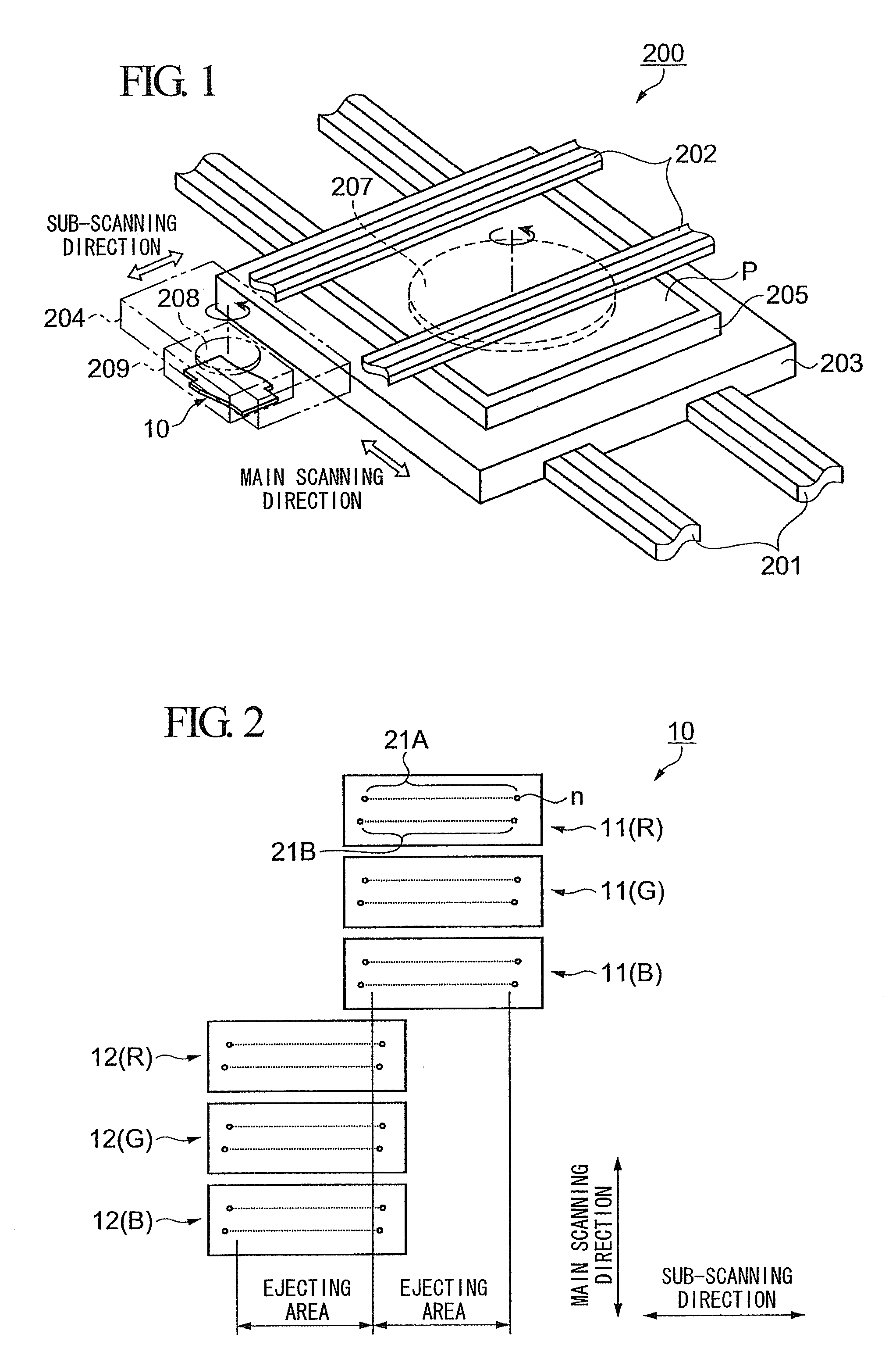
[0051]FIG. 1 is a perspective view showing the configuration of a main part of the liquid ejection device.
[0052]FIG. 2 is a plan view showing the configuration of heads in a head unit.
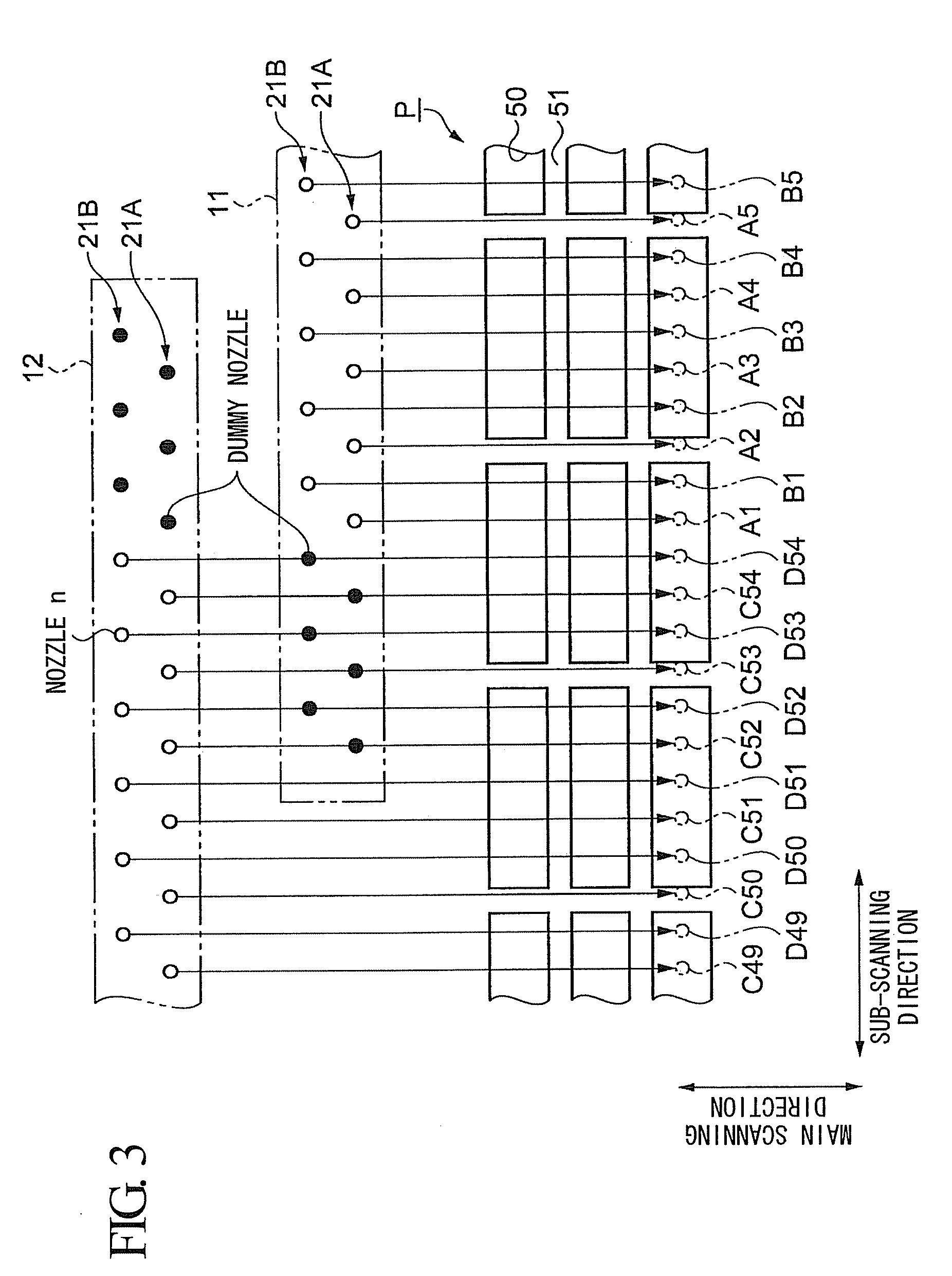
[0053]FIG. 3 is a plan view showing a positional relationship betwe...
PUM
 Abstract
Description
Claims
Application Information