Angle regulating apparatus of a display device

a display device and angle regulation technology, applied in the direction of electric apparatus casings/cabinets/drawers, instruments, machine supports, etc., can solve the problems of difficult to regulate the height or direction of the display device, and the screen on the display device does not look good

Inactive Publication Date: 2009-08-13
SE A MECHANICS
View PDF4 Cites 9 Cited by
  • Summary
  • Abstract
  • Description
  • Claims
  • Application Information

AI Technical Summary

Benefits of technology

[0011]An angle regulating apparatus of a display device according to the present invention can be adjusted to an angle suitable for a user's viewing position.
[0012]Also, the angle regulating apparatus is coupled to a height adjusting member and a fixing plate or a base, such that it can be installed on a bottom or in a space spaced apart from a ceiling by a predetermined distance. Accordingly, the angle regulating apparatus has an effect that performs a tilt-type stand function to which an existing hinge is applied.
[0013]Further, the height adjusting member itself can rotate and an angle of the display device can be regulated using a swivel of the angle regulating apparatus. Therefore, it is possible for the user to clearly watch the display device at any angles.

Problems solved by technology

However, when the conventional flat type display devices are installed on a wall, it is difficult to regulate height or direction of the display devices.
In other words, since the display devices fixedly attached on a wall do not permit a rotation, when a user watches the display devices standing aside from a front of the display device, a screen on the display devices does not look good.
Accordingly, the conventional flat type display devices have a drawback in that when a viewer who is placed at a predetermined position may inconveniently view a screen of the display device from a front side.

Method used


Image

  • Angle regulating apparatus of a display device
  • Angle regulating apparatus of a display device
  • Angle regulating apparatus of a display device

Examples


Embodiment Construction

[0048]FIGS. 9 and 10 are perspective views of a swivel in an angle regulating apparatus according to another embodiment of the present invention.

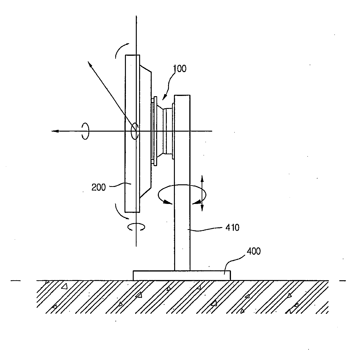
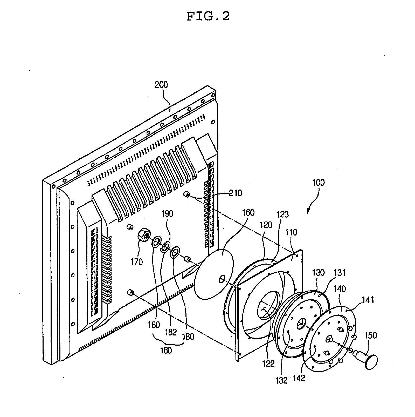
[0049]Referring to FIGS. 9 and 10, a rotatable direction of a display device 200 is determined by a shape of a penetrating opening formed at a lower portion of a swivel 120, which is an element of an angle regulating apparatus 100 according to the present invention.

[0050]In more detail, when the display device 200 installed on a wall has only to rotate in up / down or right / left direction, the penetrating opening 124 may be formed in a shape of a straight line having a predetermined width and length. In order to allow the display device 200 to rotate in up / down and right / left directions, the penetrating opening 124 may be formed in a “+” shape.

[0051]In other words, a moving path of the shaft 150 is determined by the shape of the penetrating opening 124.

[0052]The shape of the penetrating opening 124 is not limited to the embodiment of the pres...


PUM


Abstract

There is provided an angle regulating apparatus enabling a user to freely set a rotational angle and direction of a display device installed on a wall or ceiling. The angle regulating apparatus of a display device includes: a support plate coupled to a rear side of the display device; a swivel penetrating a central portion of the support plate and moving together with the support plate, the swivel being curved by a predetermined radius of curvature; a pressure plate installed in a recessed portion of the swivel, for pressurizing the swivel; a swivel holder having a front side recessed by the same radius of curvature as that of the swivel, such that the swivel is installed in the recessed portion; an attachment plate installed in a rear side of the swivel holder, for fixing the display device to a wall or ceiling; a shaft penetrating a front side of the pressure plate from a rear side of the attachment plate; and a nut inserted into an outer periphery of the shaft, for pressurizing the pressure plate. The angle regulating apparatus has an effect that it can be conveniently adjusted to an angle suitable for a user's viewing position.

Description

TECHNICAL FIELD[0001]The present invention relates to an angle regulating apparatus of a display device, and more particularly, to an angle regulating apparatus enabling a user to freely set a rotational angle and direction of a display device installed on a wall or ceiling.BACKGROUND ART[0002]In general, a display device indicates a television (TV) monitor, a computer monitor or the like. In recent years, in the case of the TV monitors, a PDP, an LCD and the like have appeared, and they are fabricated in a flat form having a larger size than that of a general CRT monitor. Since the above flat type monitors can be installed on a wall, use efficiency of inner space is enhanced.[0003]However, when the conventional flat type display devices are installed on a wall, it is difficult to regulate height or direction of the display devices. In other words, since the display devices fixedly attached on a wall do not permit a rotation, when a user watches the display devices standing aside fr...

Claims


Application Information

Patent Timeline
Patent Type & Authority Applications(United States)
IPC IPC(8): H05K5/00
CPCF16M11/12F16M11/14F16M13/027F16M11/24F16M11/2014
Inventor KIM, KYUNG WOOK
Owner SE A MECHANICS
Why Eureka
Try Eureka