
Resilient provider link state bridging (PLSB) virtual private LAN service (VPLS) interworking

a provider link state and interworking technology, applied in the field of provider link state bridging and virtual private lan service (vpls) network domains, can solve problems such as poor scaling, inefficient flooding of frames, and already severe scaling limitations

Inactive Publication Date: 2009-08-13
RPX CLEARINGHOUSE
View PDF22 Cites 53 Cited by
  • Summary
  • Abstract
  • Description
  • Claims
  • Application Information

AI Technical Summary

Benefits of technology

"The present invention provides a method for interfacing two different network domains using Ethernet Bridging and Link-State controlled network domains. The method involves creating attachment points between the two domains and representing them as virtual nodes connected through virtual links. The virtual links are configured so that frames from one domain are forwarded through only one attachment point in the other domain. This allows for efficient communication between the two domains. The invention also provides scenarios for both UNI and NNI interworking, with different levels of detail depending on the specific needs of the network. Overall, the invention improves network efficiency and reliability."

Problems solved by technology

A problem with VPLS is that it scales poorly, in particular because customer Media Access Control (C-MAC) addresses are exposed to the VPLS domain.
Finally the full mesh of pseudo wires means that any flooding of frames is inefficient, as all frame replication must be performed at the ingress to the pseudo-wire mesh.
This approach has the penalty alluded to above, in that the gateways between edge and core are exposed to the full range of C-MAC addresses, which was already a severe scaling limitation.
It also introduces additional complexity to address resiliency issues as it requires multi-homing of the spokes onto the core mesh.
However the deployment of PBB overlaid on existing VPLS suffers limitations in that interworking between a PBB Network and legacy ports (i.e. where the peer VPLS Provider Edge router, PE, is not configured to support Backbone Edge Bridging) presents numerous challenges and complexity, and in any case the combination of VPLS and PBB only has the capability to address some of the scaling issues of VPLS.

Method used


Image

  • Resilient provider link state bridging (PLSB) virtual private LAN service (VPLS) interworking
  • Resilient provider link state bridging (PLSB) virtual private LAN service (VPLS) interworking
  • Resilient provider link state bridging (PLSB) virtual private LAN service (VPLS) interworking

Examples


Embodiment Construction

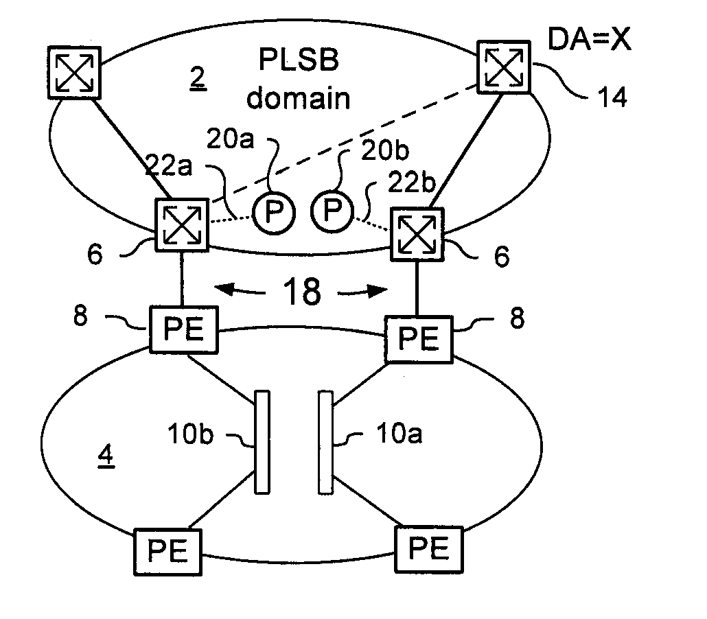
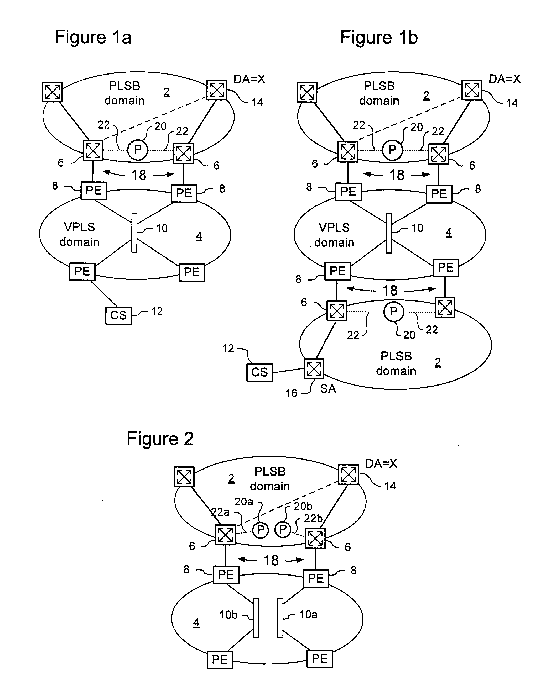
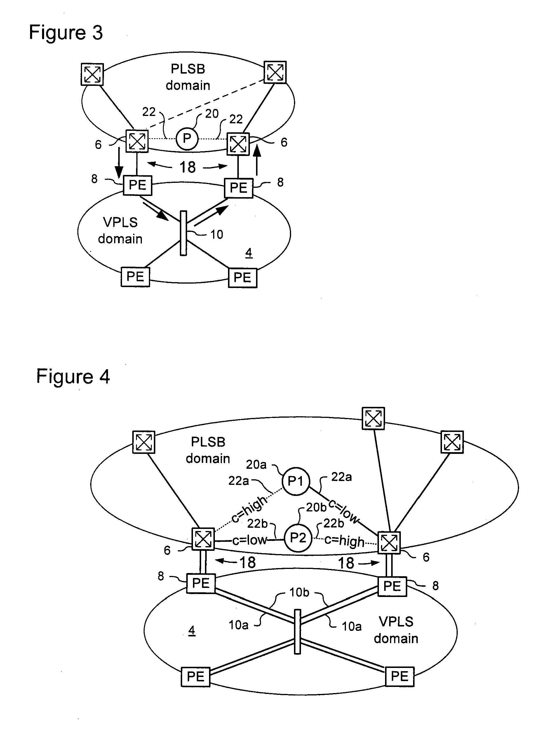
[0025]The present invention provides a method for management of traffic forwarding in frame networks, and in particular to methods of interfacing Link State protocol controlled network domains and Virtual Private LAN Service (VPLS) network domains. Embodiments of the invention are described below, by way of example only, with reference to FIGS. 1-4.

[0026]PLSB as described in Applicant's co-pending U.S. patent application Ser. No. 11 / 537,775 provides a link state control plane for Ethernet networks using IS-IS to disseminate information that permits local computation and set up unicast paths and multicast trees in the network. The above patent document is hereby incorporated by reference. Like PBB, PLSB uses encapsulation to hide the C-MAC address spaces from the backbone operator network, facilitating scalability and security. PLSB is a “routed” infrastructure technology; and the IS-IS control plane makes nodes aware of the network topology, and the route to any specific B-MAC addre...


PUM


Abstract

A method of peer interfacing a Link-State controlled network domain with an Ethernet Bridging controlled network domain. A pair of peer attachment points are provided between the Link-State controlled network domain and the Ethernet Bridging domain. The peer attachment points are respective endpoints of a set of one or more LAN segments defined within the Ethernet Bridging domain. The set of LAN segments are represented as a virtual node in the Link-State controlled network domain. The virtual node is represented in the Link-State controlled network domain as connected to each of the peer attachment points via a respective virtual link. The virtual links are configured such that frames to or from an address in the Link-State controlled network domain are forwarded over a tree passing through only one of the peer attachments points.

Description

CROSS-REFERENCE TO RELATED APPLICATIONS[0001]This application is based on, and claims priority of British Patent Application No. 0802371.5 filed Feb. 9, 2008.MICROFICHE APPENDIX[0002]Not Applicable.TECHNICAL FIELD[0003]The present invention relates to management of traffic forwarding in frame networks, and in particular to methods of interfacing Provider Link State Bridging (PLSB) and Virtual Private LAN Service (VPLS) network domains.BACKGROUND OF THE INVENTION[0004]Network operators and carriers are deploying frame-switched communications networks in place of circuit-switched networks. In frame-switched networks such as Internet Protocol (IP) networks, IP frames are forwarded according to routing state stored at each IP router in the network. Similarly, in Ethernet networks, Ethernet frames are forwarded according to forwarding state stored at each Ethernet switch in the network. The present invention applies to communications networks employing any Protocol Data Unit (PDU) based ...

Claims


Application Information

Patent Timeline
Patent Type & Authority Applications(United States)
IPC IPC(8): H04L12/56H04L45/24H04L45/28
CPCH04L12/4625H04L45/12H04L47/125H04L45/28H04L45/22
Inventor BRAGG, NIGEL L.ALLAN, DAVIDASHWOOD SMITH, PETERUNGEHAGEN, PAUL
Owner RPX CLEARINGHOUSE
Learn More