Manual provision method, peripheral device, and control program

a technology of manuals and peripheral devices, applied in the direction of instruments, computing, electric digital data processing, etc., can solve the problems of increasing the size of manuals, troublesome user referring to two different manuals, and difficulty in user finding the desired items, etc., to achieve the effect of convenient referen

Inactive Publication Date: 2009-08-13
KONICA MINOLTA BUSINESS TECH INC
View PDF17 Cites 30 Cited by
  • Summary
  • Abstract
  • Description
  • Claims
  • Application Information

AI Technical Summary

Benefits of technology

[0024]According to the present invention, a user that operates an application that runs by accessing a multi-function peripheral can easily refer to a desired item in a manual.

Problems solved by technology

However, with manual booklets, there are situations where it is difficult for the user to find the desired items, such as when the table of contents or index lacks sufficient depth, the user only knows part of the desired term, and so on.
Referring to two different manuals is troublesome for the user.
Furthermore, recent years have seen an increase in the functions provided by multi-function peripherals and applications, which has led to an increase in the size of manuals.
Therefore, it is becoming increasingly difficult to find desired items in manuals, even if those manuals are electronic manuals.

Method used


Image

  • Manual provision method, peripheral device, and control program
  • Manual provision method, peripheral device, and control program
  • Manual provision method, peripheral device, and control program

Examples


first embodiment

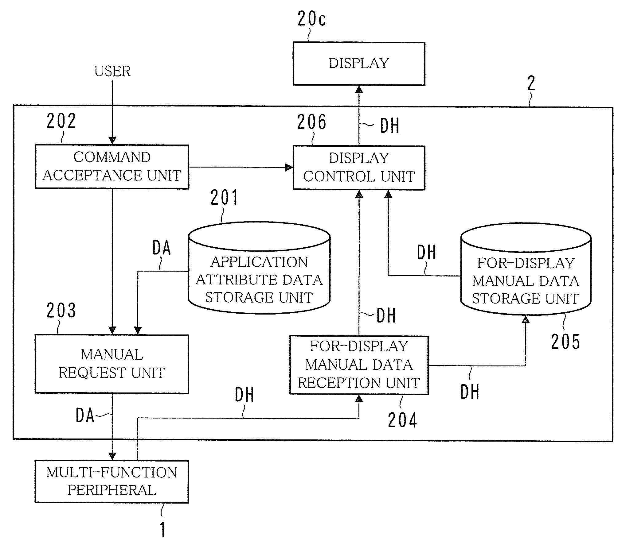
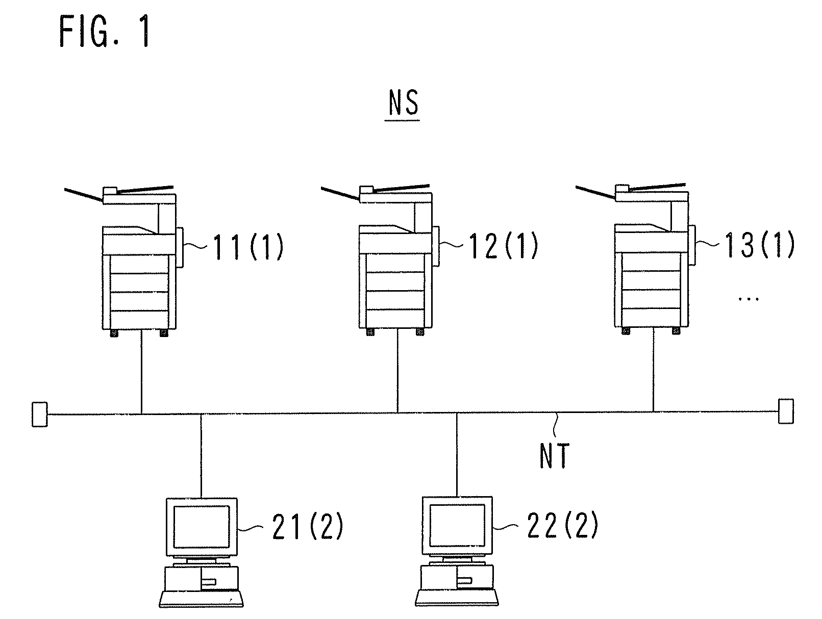
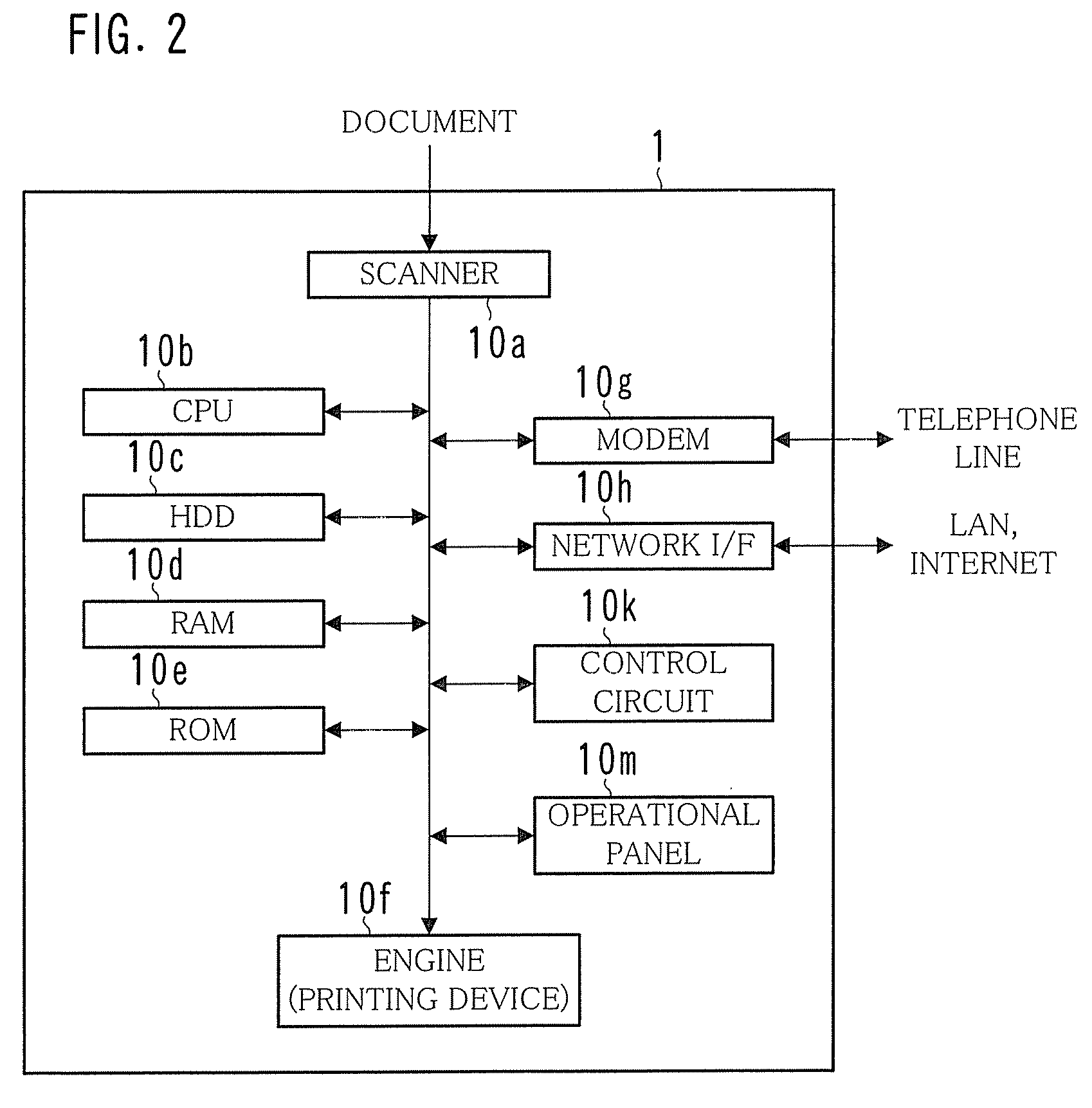
[0041]FIG. 1 is a diagram showing an example of the overall configuration of a network system NS; FIG. 2 is a diagram illustrating an example of a hardware configuration of a multi-function peripheral 1; FIG. 3 is a diagram showing an example of the functional configuration of the multi-function peripheral 1; FIG. 4 is a diagram illustrating an example of a hardware configuration of a terminal device 2; and FIG. 5 is a diagram showing an example of the functional configuration of the terminal device 2.

[0042]The network system NS is configured of multi-function peripherals 11, 12, and so on; terminal devices 21, 22, and so on; and a communication line NT. The multi-function peripherals 11, 12, and so on may be collectively referred to as a “multi-function peripheral 1” hereinafter. Similarly, the terminal devices 21, 22, and so on may be collectively referred to as a “terminal device 2” hereinafter. Other devices, data, or the like may also be collectively described in the same manne...

second embodiment

[0112]FIG. 13 is a diagram showing an example of the overall configuration of a network system NS′; FIG. 14 is a diagram illustrating an example of a functional configuration of a multi-function peripheral 1B; and FIG. 15 is a diagram illustrating an example of the functional configuration of a manual management server SA.

[0113]In the first embodiment, each multi-function peripheral 1 manages the manual data DM on its own manuals. However, in the second embodiment, a manual management server SA is provided in the network system NS′, and the manual data DM on each multi-function peripheral 1B is collectively managed by the manual management server SA, as shown in FIG. 13.

[0114]Hereinafter, the multi-function peripheral 1B, a terminal device 2B, and the manual management server SA shall be described, focusing on the differences between the first embodiment and the present embodiment. Descriptions of points common between the two embodiments shall be omitted.

[0115]The multi-function pe...


PUM


Abstract

A terminal device used by a user transmits identification information on an application used along with a multi-function peripheral by the terminal device to that multi-function peripheral. The multi-function peripheral then transmits, to the terminal device, for-display manual data on a manual corresponding to the application indicated by the identification information received from the terminal device.

Description

[0001]This application is based on Japanese Patent Application No. 2008-030230 filed on Feb. 12, 2008, the contents of which are hereby incorporated by reference.BACKGROUND OF THE INVENTION[0002]1. Field of the Invention[0003]The present invention relates to a method for providing, to a user, a manual for a peripheral device used with a personal computer or the like.[0004]2. Description of the Related Art[0005]At present, various peripheral devices, such as printers, card readers, multi-function peripherals, and so on, are being used with personal computers.[0006]Manuals for such peripheral devices are provided to users in printed form, as manual booklets, or are recorded onto an electronic medium such as a CD-ROM and provided to users in electronic form. Manuals are also sometimes provided through the manufacturer's web site. Manuals provided through electronic media or web sites are generally called “electronic manuals”.[0007]Compared to providing users with manuals in booklet for...

Claims


Application Information

Patent Timeline
Patent Type & Authority Applications(United States)
IPC IPC(8): G06F3/00
CPCG06F9/4446G06F9/453
Inventor MOCHIZUKI, TAKATOSHI
Owner KONICA MINOLTA BUSINESS TECH INC
Why Eureka
Try Eureka