
By-pass and pressure regulator valve

a pressure regulator and bypass valve technology, applied in the direction of ratio control, thin material handling, instruments, etc., can solve the problems of obvious annulation of flow pressure loss, very simple and reliable construction, and very low reliability, and achieve easy and accurate calibration of the device. , high reliability

Active Publication Date: 2009-08-20
P A SPA
View PDF7 Cites 4 Cited by
  • Summary
  • Abstract
  • Description
  • Claims
  • Application Information

AI Technical Summary

Benefits of technology

"The present invention is a by-pass and pressure regulator valve for high-pressure washing plants. The valve has limited flow pressure loss, which is similar to that of a normal unloader valve, and can be calibrated with extreme precision. The valve is designed to control the operating pressure with the gun open and to prevent excessive energy consumption and pump overheating. The valve is also designed to allow for the separation of the pilot piston from the contrast spring, which is necessary for closure of the by-pass, but this leads to an increase in size and complexity of the valve. The valve of the present invention solves these drawbacks in the prior art."

Problems solved by technology

Devices of this type, however constructionally very simple and reliable they are, exhibit an obvious drawback; the delivery channel upstream of the gun stays at high pressure, with obvious problems in terms of safety and ease of use.
The flow pressure loss is obviously annulled with the closure of the gun and the consequent interruption of the fluid flow.
The above-described valve exhibits, however, a substantial problem: to keep the obturator closed the regulator spring has to be contrasted.
Since this is usually a rather strong spring, the flow pressure loss generated by the device has to be quite strong.
There is a consequent considerable reduction in the dispensing pressure of the washing fluid, which causes a high consumption of energy and leads to problems of overheating in the plant's pump.
Further, as it is always necessary to have large flow pressure loss in order to guarantee the obturator seal on the by-pass seating, plant functioning problems may ensue at low flow rates.
In this case, however, the mechanism is particularly sensitive and has therefore to be calibrated with extreme precision.
With respect to this necessity, known-type valves are limited by the variations in the flow pressure loss due to fluctuations in the fluid flow rate and functioning irregularities due to contact of one of the pilot piston surfaces with the fluid in motion.
The presence of two distinct mechanisms leads however to an undesired increase in size and an excessive constructional complexity.

Method used


Image

  • By-pass and pressure regulator valve
  • By-pass and pressure regulator valve
  • By-pass and pressure regulator valve

Examples


Embodiment Construction

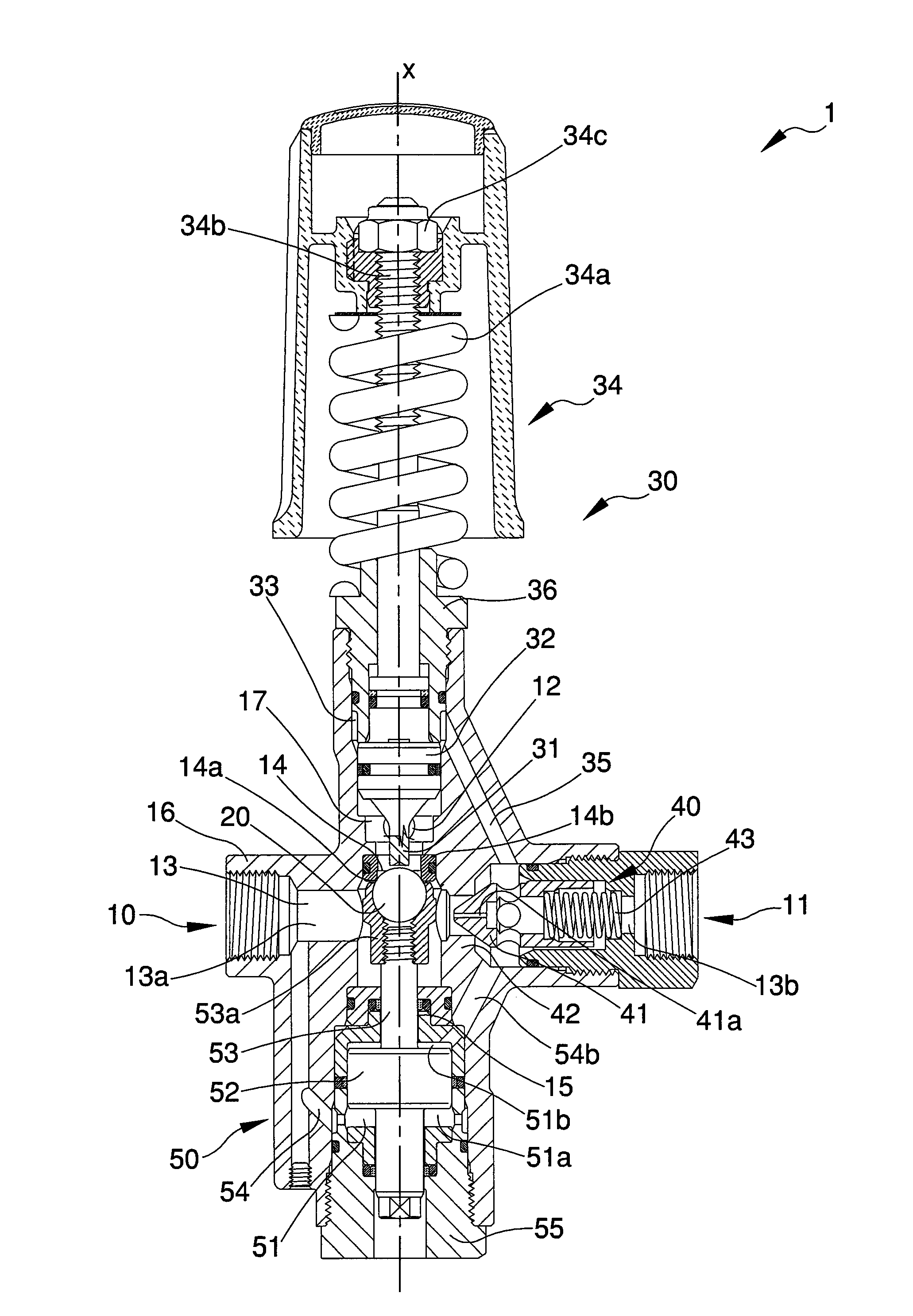
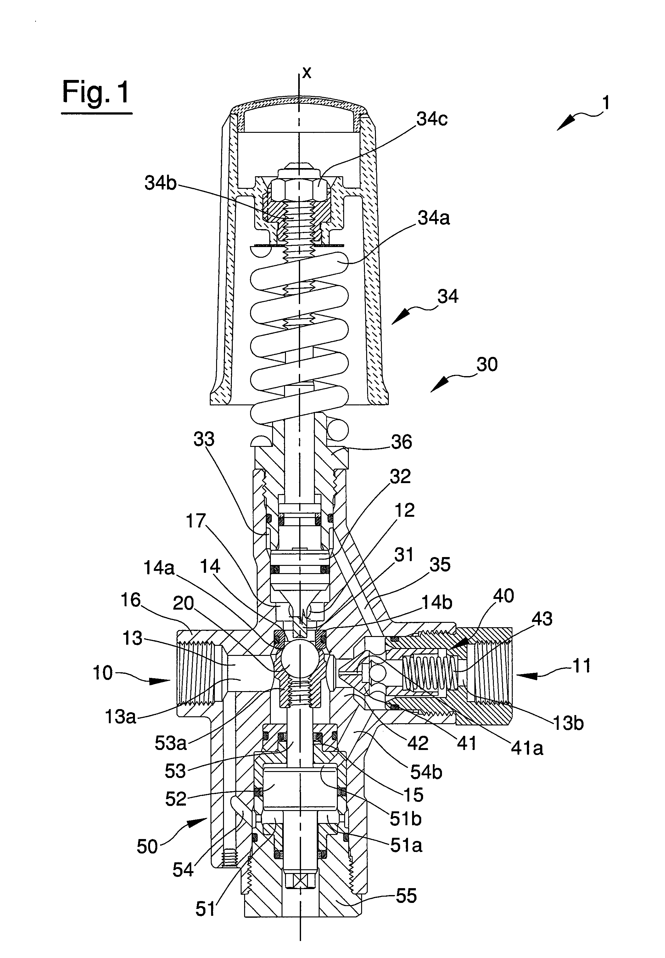
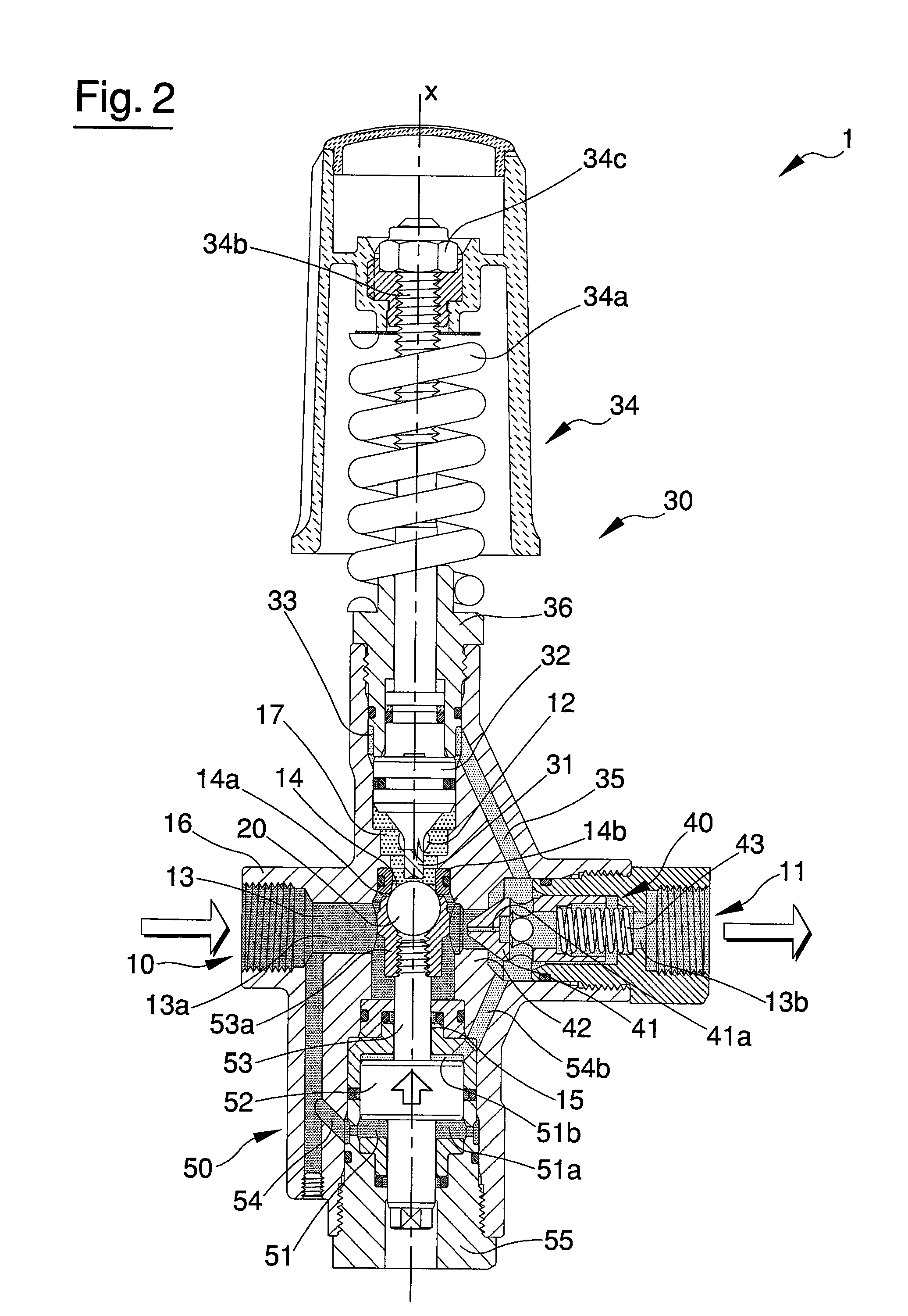
[0025]With reference to the figures of the drawings, 1 denotes a by-pass and pressure regulator valve of the present invention. In particular, the valve is predisposed to reduce the pressure in the delivery branch up to levels just above atmospheric pressure when the gun in the associated circuit is closed, i.e. it is of the type of valves commonly known as reset valves.

[0026]The device is illustrated in a preferred operating configuration. The positional relations among elements of the by-pass and pressure regulator valve 1 described herein below in terms of relative height (for example by the use of words such as “lower” or “upper” are to be interpreted at all times with reference to this configuration.

[0027]The by-pass and pressure regulator valve 1 of the invention exhibits an inlet mouth 10 and an outlet mouth 11 set in reciprocal communication by a main conduit 13; it is further provided with a by-pass mouth 12.

[0028]The by-pass and pressure regulator valve 1 comprises an obtu...


PUM


Abstract

A by-pass and pressure regulator valve exhibiting: an inlet mouth and an outlet mouth set in reciprocal communication by a main conduit; a by-pass mouth. The by-pass and pressure regulator valve comprises: an obturator, mobile between at least a closed position, in which it interrupts fluid communication between the main conduit and the by-pass mouth, and at least an open position, in which the fluid communication is not interrupted; operating pressure control means, predisposed to move the obturator from the closed position; means for determining a flow pressure loss in fluids crossing the main conduit, arranged along the main conduit in order to separate a first tract upstream of the main conduit from a second tract downstream thereof; obturator command means governed by a fluid pressure difference between the first tract and the second tract of the main conduit, distinct from the operating pressure control means but operatively connected to the obturator.

Description

BACKGROUND OF THE INVENTION[0001]The object of the present invention is a by-pass and pressure regulator valve. In particular, the valve is usefully applied internally of hydraulic circuits for high-pressure washing.[0002]High-pressure washing plants generally comprise a piston pump, destined to place a washing fluid under pressure, a valve of the type of the invention and a lever tap valve, commonly called a gun, which is predisposed to enable an operator to control dispensing of the fluid.[0003]Unless electrical devices are included for automatic turning-off of the pump, the pump operates continuously and thus remains in operation even when the gun is turned off by the operator; given the incompressibility of the fluid, it is necessary for it to be discharged into a low-pressure tank through a by-pass conduit. The opening of the conduit it controlled by a valve, simply known as a by-pass or unloader valve.[0004]The valve is also used for control of the operating pressure with the ...

Claims


Application Information

Patent Timeline
Patent Type & Authority Applications(United States)
IPC IPC(8): G05D11/00
CPCG05D16/10Y10T137/2516Y10T137/2605Y10T137/2647Y10T137/265
Inventor BENETTI, ARNALDO
Owner P A SPA
Learn More