Variable-length control arm

a control arm and variable-length technology, applied in the direction of resilient suspensions, vehicle springs, vehicle components, etc., can solve the problems of achieving mediocre performance in more than one field of use, limiting recreation vehicles, and often limiting sport-utility vehicles to trucks and sport-utility vehicles. achieve the effect of increasing the stance and wheelbase of the vehicle, and increasing the ride height and stance of the vehicl

Inactive Publication Date: 2009-08-20
MERRYMAN FORREST DERRY
View PDF42 Cites 4 Cited by
  • Summary
  • Abstract
  • Description
  • Claims
  • Application Information

AI Technical Summary

Benefits of technology

[0049]FIG. 6 is a more detailed representation of the second figure and utilizes the object in FIG. 5. Object 6-A resembles a vehicle using the variable-length control arm in their contracted configuration. Object 6-B resembles the same vehicle using the control arms in their expanded configuration, achieving greater ride height, stance, and wheelbase of the vehicle.
[0050]FIG. 7 is another more detailed depiction of FIG. 2 in that the expansion increases the vehicle's stance and wheelbase. Though resembling FIG. 6, it has two pivot arms moved by hydraulics. It shows two of the stages, fully contracted and full extended (Object 7-A and Object 7-B, respectively).

Problems solved by technology

Recreational vehicles, meant to be the most capable off of paved roads, are often limited to trucks and sport-utility vehicles.
These vehicles have been engineered by their manufacturers first and foremost to handle safely on the road while having their limited off-road capability for recreation.
The setups' capabilities are well rounded, thus achieving mediocre performances in more than one field of use.
This raises the chassis higher from the frame; therefore, it is a less functional modification and is only suitable for certain vehicles.
They require the altered vehicles to be best capable in off-road use and limited in road use; therefore, making the vehicle permanently dangerous on public roads.
The additional lift increases the vehicle's bumper height, adding risk to other lower vehicles which may have a collision with the lifted vehicle.
Also, the lifted vehicle's center of gravity is raised, making the vehicle more liable to overturn.
Lastly, the altercations go against many manufacturers' warranties, reinforcing the idea that the oversized vehicles are not safe to operate on public roads.
This functionality problem arises when people have a desire for improved off road capabilities.
They either modify their personal vehicles or utilize a preexisting chassis for off road use; these are also known as “trail rigs.” These methods require much more labor and are not cost effective.
To modify a commonly used vehicle is expensive and voids many warranties.
However, more space is needed to store the vehicle.
Many problems arise when the vehicle's owner requires improved recreational capabilities off of the paved road.
These ways to improve ride height, articulation, and the application of larger tires for recreational purposes provide for many disadvantages of everyday use:1. The altercations described above limit the safe use of the vehicle to only off of the road at slower speeds.
The vehicle's capability is not nearly as safe as the manufacturer's engineered use on public roads.
The increased ride height makes the altered vehicle's higher bumper height a clear and present danger for smaller vehicles such as family cars and vans.C.
The increased ride height causes smaller vehicles to be dangerously hidden in blind spots in the more frequently use on roads.2. The altercations of the parts of the vehicles provide for many difficulties in value of the vehicle and provide for many costs.
Moderate to extreme altercations made to a vehicle are not cost effective due to the price of the replacement parts and the added effort of the installation.B.
An altered vehicle is difficult to restore to its original condition and value since these needed fabrications and parts are designed to be more permanent and survive the extended use.C.
The altercations made specifically to the suspension and drive train of a vehicle void many warranties provided for by the manufacturers of the vehicles, discouraging recreation.

Method used


Image

  • Variable-length control arm
  • Variable-length control arm
  • Variable-length control arm

Examples


Embodiment Construction

[0053]In the past, the only way a vehicle could change to better accommodate its passengers through the environment was to change between two-wheel, four-wheel, or all-wheel drive. Not only does my invention allow for changing the way power is distributed to the wheels, but also allowing that vehicle to alter properties of its suspension to better handle the many environments. This invention can be utilized by all sorts of vehicles, from remote-controlled toys all the way to full-size vehicles found on the road.

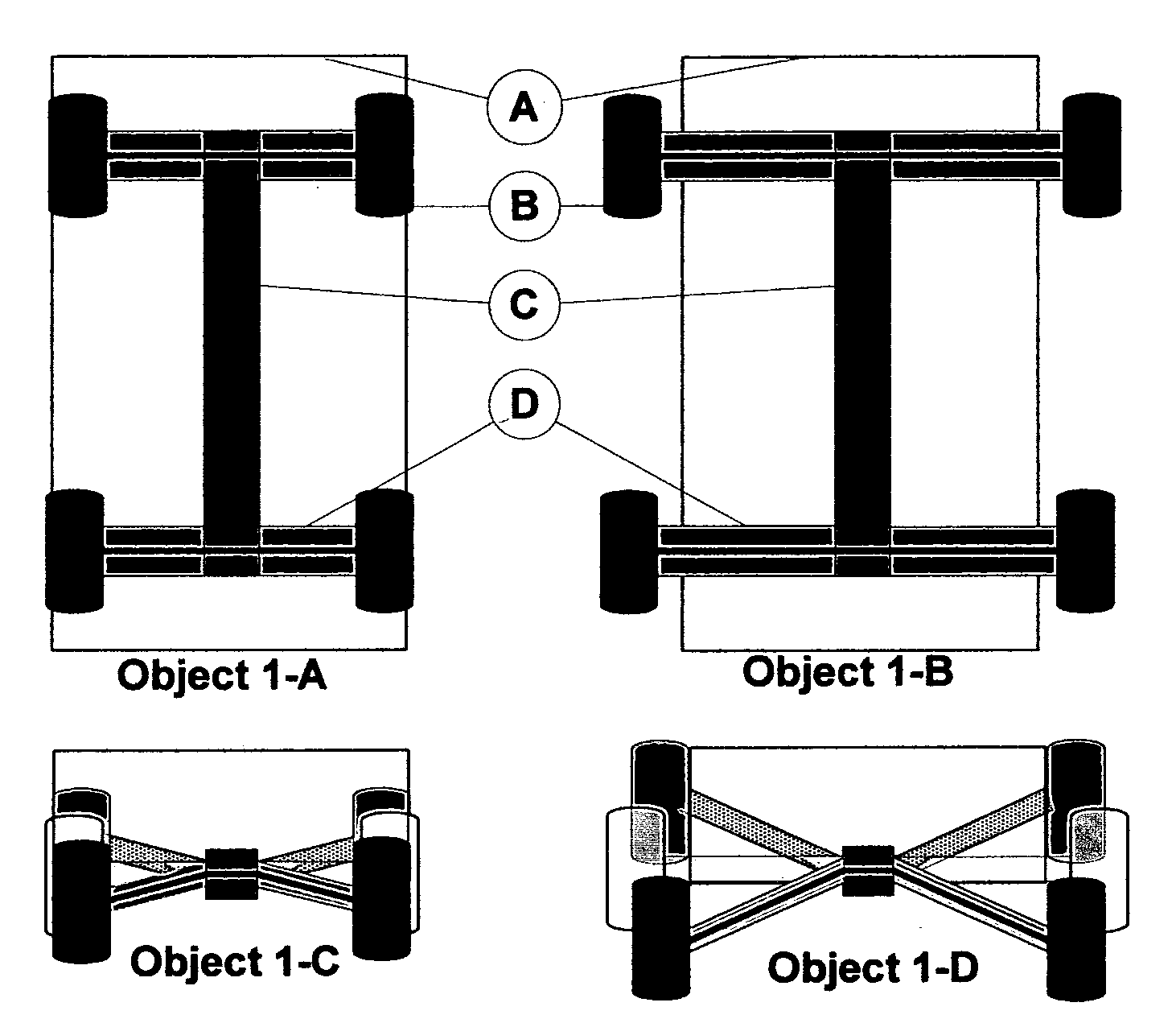
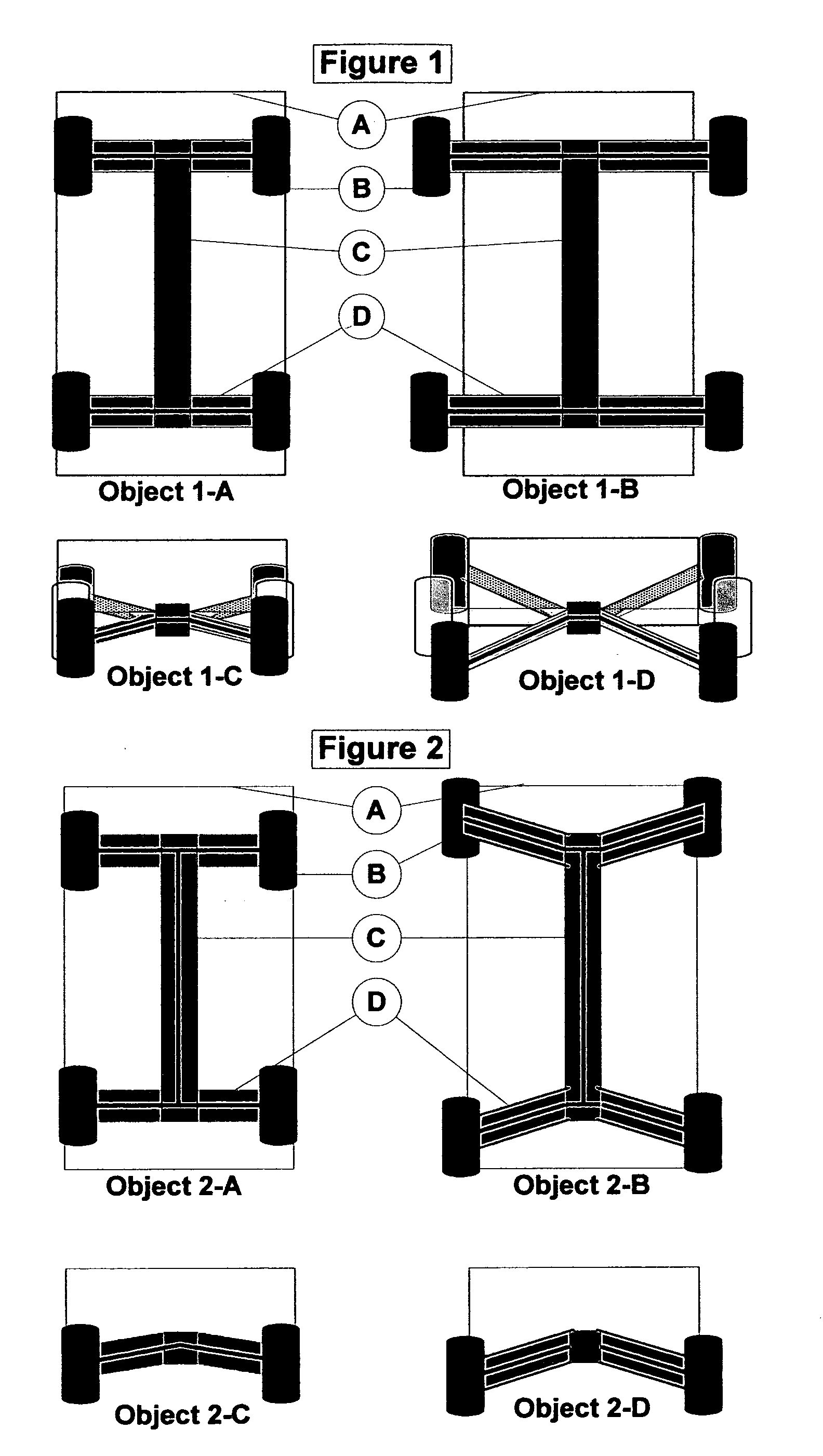
[0054]The invention relates to the idea of expansion and contraction. Like many industrial vehicles like tractors and dump trucks, this expansion may be powered by hydraulics. Many other methods of expansion may be used, such as rotational movement, or other means of manual change.

[0055]FIGS. 1 and 2 vaguely depict two vehicles that undergo changes. The vehicle on the right lengthens its control arms' lengths and changes its tire placement. FIG. 1 shows how relocating the tir...


PUM


Abstract

Before, vehicles with independent suspensions could not alter the tire's positions. Modifications or use of aftermarket parts were needed for the vehicle to perform under more extreme conditions such as gaining clearance for off road use or squatting down low for a wide, racy stance. My invention will allow many scenarios of suspension types to be used on a single vehicle, with a single suspension system. The control arms are fixable in length allowing many variances in ride height, stance and wheelbase. This will broaden the vehicle's purpose and capabilities and will make many aftermarket upgrades to the vehicle unnecessary.

Description

CROSS-REFERENCE TO RELATED APPLICATIONS [0001]Not ApplicableFEDERALLY SPONSORED RESEARCH [0002]No aid of sponsorship of any kind was used.SEQUENCE LISTING OR PROGRAM [0003]Not ApplicableBACKGROUND OF THE INVENTION[0004]1. Field of Invention[0005]This invention relates to an improvement on vehicles' independent suspension systems, specifically allowing a vehicle's undercarriage to convert between two or more scenarios of suspension and drive train desirable for its needed capabilities.[0006]2. Prior Art[0007]Recreational vehicles, meant to be the most capable off of paved roads, are often limited to trucks and sport-utility vehicles. These vehicles have been engineered by their manufacturers first and foremost to handle safely on the road while having their limited off-road capability for recreation. They employ four wheel or all wheel drive using the following: solid axles with a leaf spring suspension, free axles with independent suspension, or a front and rear combination of both....

Claims


Application Information

Patent Timeline
Patent Type & Authority Applications(United States)
IPC IPC(8): B60G7/00
CPCB60G2300/40B60G1/00B60G3/18B60G7/003B60G2200/1442B60G2202/44
Inventor MERRYMAN, FORREST DERRY
Owner MERRYMAN FORREST DERRY
Why Eureka
Try Eureka