Fusing device and image forming apparatus using the same

a technology of fusing device and forming apparatus, which is applied in the direction of electrographic process apparatus, instruments, optics, etc., can solve the problems of unstable fusing operation, inability to keep the pressing force and the nip width constant at any time, and partial permanent deformation of the elastic layer formed on the outer periphery of the roller member, so as to prevent the occurrence of partial permanent deformation, stable fusing operation, and simple structure

Inactive Publication Date: 2009-08-20
SHARP KK
View PDF4 Cites 1 Cited by
  • Summary
  • Abstract
  • Description
  • Claims
  • Application Information

AI Technical Summary

Benefits of technology

[0018]According to the first aspect of the present invention, since no pressing force greater than needed will be applied between the roller members, it is possible to prevent occurrence of partial permanent deformation in the elastic layers of the roller members, hence achieve a stable fusing operation.
[0019]According to the second aspect of the present invention, since no pressing force greater than needed will be applied between the roller members without the necessity of providing a separate regulator and the like for regulating the press-contact state of the roller members, it is possible with a simple structure to prevent occurrence of partial permanent deformation in the elastic layers of the roller members.
[0020]According to the third aspect of the present invention, since no pressing force greater than needed will be applied between the roller members, it is possible to prevent occurrence of partial permanent deformation in the elastic layers of the roller members.
[0021]According to the fourth aspect of the present invention, it is possible to assure the nip width necessary for fusing by thermal expansion of the roller members when a fusing operation is performed by the paired roller members.
[0022]According to the fifth aspect of the present invention, since as table fusing operation can be carried out by preventing occurrence of partial permanent deformation in the elastic layers of the roller members, it is possible to provide an image forming apparatus which can stably achieve high-quality image printing with toner images reliably fused and fixed.

Problems solved by technology

However, the above conventional fusing device suffers the problem that pressing the roller members against each other for many hours by use of a pressing member such as a spring etc., causes partial permanent deformation in the elastic layer formed on the outer periphery of the roller member.
However, in this prior art, the nip portion is created by causing the roller member to thermally expand without use of any pressing element such as a spring or the like, it is hence impossible to keep the pressing force and the nip width constant at any time.
As a result there has been the problem that the fusing operation is unstable.

Method used


Image

  • Fusing device and image forming apparatus using the same
  • Fusing device and image forming apparatus using the same
  • Fusing device and image forming apparatus using the same

Examples


first exemplary embodiment

The First Exemplary Embodiment

[0066]Firstly, the first exemplary embodiment will be described with reference to the drawings.

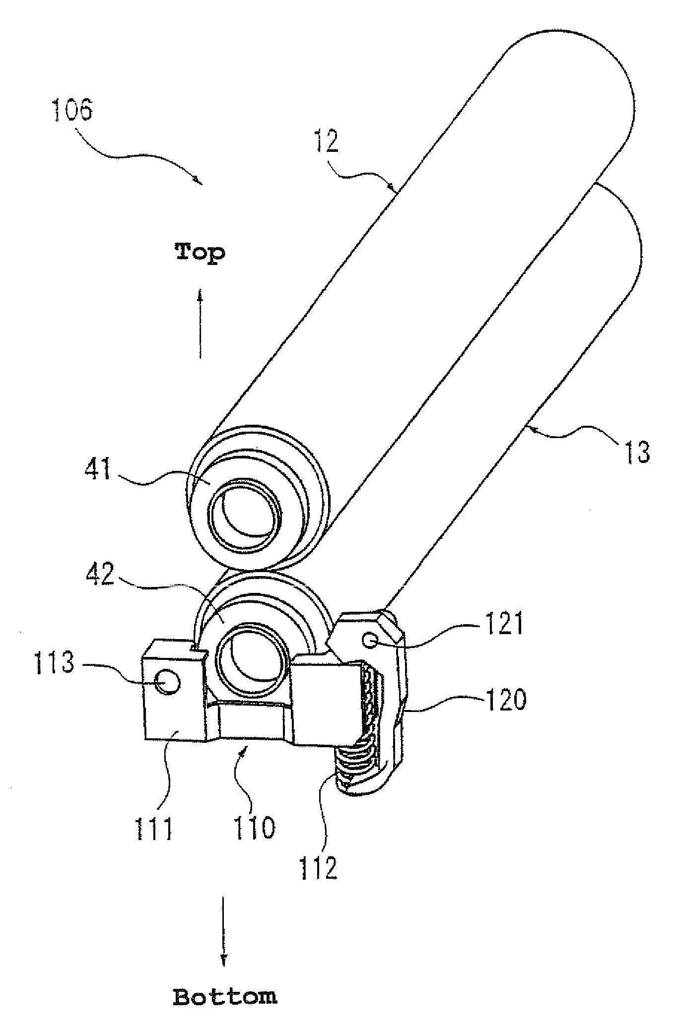
[0067]FIG. 4 is a perspective view showing the configuration of the first exemplary embodiment of a fusing unit of the image forming apparatus according to the present embodiment. FIG. 5 is an illustrative view showing the configuration of the fusing unit, viewed from the direction of the roller axis.

[0068]As shown in FIGS. 4 and 5, a fusing unit (fusing device) 106 of the first exemplary embodiment includes a pressing structure 110 for arranging rotatable fusing roller 12 and pressing roller 13 so as to oppose each other and put pressing roller 13 into press-contact with fusing roller 12, a pressure release lever (pressure release member) 120 serving as a pressing structure regulator to regulate the pressing action of pressing structure 110 and a pressure release lever positioning pin (pressure release member regulator) 130 for regulating the action of pressu...

second exemplary embodiment

The Second Exemplary Embodiment

[0093]Next, the second exemplary embodiment will be described with reference to the drawings.

[0094]FIG. 7 is a perspective view showing the configuration of the second exemplary embodiment of a fusing unit according to the present embodiment, and FIG. 8 is an illustrative view showing the configuration of the fusing unit of the second exemplary embodiment, viewed from the direction of the roller axis.

[0095]Here in the second exemplary embodiment, the same components as those in the first exemplary embodiment are allotted with the same reference numerals, so that their description is omitted.

[0096]As shown in FIGS. 7 and 8, a fusing unit (fusing device) 206 of the second exemplary embodiment includes a pressing structure 110 for arranging rotatable fusing roller 12 and pressing roller 13 so as to oppose each other and put pressing roller 13 into press-contact with fusing roller 12 and a pressing roller side frame (frame structure) 210 for regulating the...

third exemplary embodiment

The Third Exemplary Embodiment

[0104]Next, the third exemplary embodiment will be described with reference to the drawings.

[0105]FIG. 9 is a perspective view showing the configuration of the third exemplary embodiment of a fusing unit according to the present embodiment, and FIG. 10 is an illustrative view showing the configuration of the fusing unit, viewed from the direction of the roller axis.

[0106]Here in the third exemplary embodiment, the same components as those in the first and second exemplary embodiments are allotted with the same reference numerals, so that their description is omitted.

[0107]As shown in FIGS. 9 and 10, a fusing unit (fusing device) 306 of the third exemplary embodiment includes a pressing structure 110 for arranging rotatable fusing roller 12 and pressing roller 13 so as to oppose each other and put pressing roller 13 into press-contact with fusing roller 12, and a fusing roller side frame (frame structure) 310 for regulating the pressing action of pressin...


PUM


Abstract

A fusing unit is comprised of a fusing roller and a pressing roller, having an elastic layer on their outer peripheral surface and a pressing structure for pressing the fusing roller against the pressing roller, and causes a sheet of paper with an unfixed toner image to pass through the nip portion where the fusing roller and pressing roller are put in press-contact with each other so as to fuse the toner image and fix it to the paper. This fusing unit further includes a pressure release lever for regulating the pressing action of the pressing structure when the rollers are put in press-contact with each other by the pressing structure.

Description

[0001]This Nonprovisional application claims priority under 35 U.S.C. 119(a) on Patent Application No. 2008-032575 filed in Japan on 14 Feb. 2008, the entire contents of which are hereby incorporated by reference.BACKGROUND OF THE INVENTION[0002](1) Field of the Invention[0003]The present invention relates to a fusing device and an image forming apparatus using the fusing device, and in particular relates to a fusing device that includes a pair of roller elements functioning as a fusing roller and a pressing roller to pass a recording medium with an unfixed toner image formed thereon to the contact nip where these roller elements are put in contact with each other, to thereby fix the toner image formed on the recording thereto, as well as relating to an image forming apparatus using this fusing device.[0004](2) Description of the Prior Art[0005]Conventionally, in image forming apparatus using electrophotography, such as facsimile machines, printers, etc., an image is output on a rec...

Claims


Application Information

Patent Timeline
Patent Type & Authority Applications(United States)
IPC IPC(8): G03G15/20
CPCG03G15/206G03G15/2032
Inventor NAMISAKI, KOUSUKETATEISHI, YOSHINOBU
Owner SHARP KK
Why Eureka
Try Eureka