Leather And Manufacturing Method Of Leather

a manufacturing method and leather technology, applied in the field of leather, can solve the problems of inaccurate shape, inability to form the folded portion, and inability to accurately shape the /b>

Inactive Publication Date: 2009-08-27
MIDORI ANZEN
View PDF11 Cites 4 Cited by
  • Summary
  • Abstract
  • Description
  • Claims
  • Application Information

AI Technical Summary

Benefits of technology

[0014]The present invention has been achieved in view of the above described problems, and has an object to provide a leather in which a shape of a folded portion provided at an edge section is accurate, and a manufacturing method of that leather, in a leather for covering a shift knob or a steering wheel.

Problems solved by technology

Namely, in the conventional leather 200, there has been a problem that there are cases where the folded portion 202 cannot be formed in an accurate shape.
In this way, when the folded portion 202 is formed in an inaccurate shape, the shape of the entire leather 200 becomes inaccurate, and when it is adhered to the core member of the steering wheel, the appearance of the steering wheel will be spoiled as there is a gap between leathers or the leathers overlap, and the feel is also deteriorated as an unnecessary hooking portion is formed so that a fingertip will be hooked.
The steering wheel having these problems will be a component for a car or the like to be described below, and as it has problems at portions to be directly touched by hand of a driver, it will be an obstacle at a time of driving a car safely so that it will not be a commercial product.
Note that the problems described above are problems not only for the steering wheel but also for the leather to be used on a shift knob or the leather without the sewing with stitches that can occur similarly.

Method used


Image

  • Leather And Manufacturing Method Of Leather
  • Leather And Manufacturing Method Of Leather
  • Leather And Manufacturing Method Of Leather

Examples


first embodiment

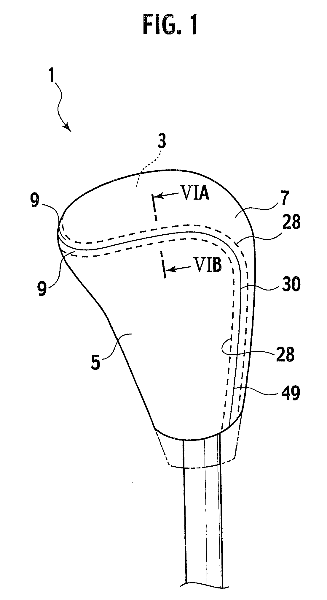
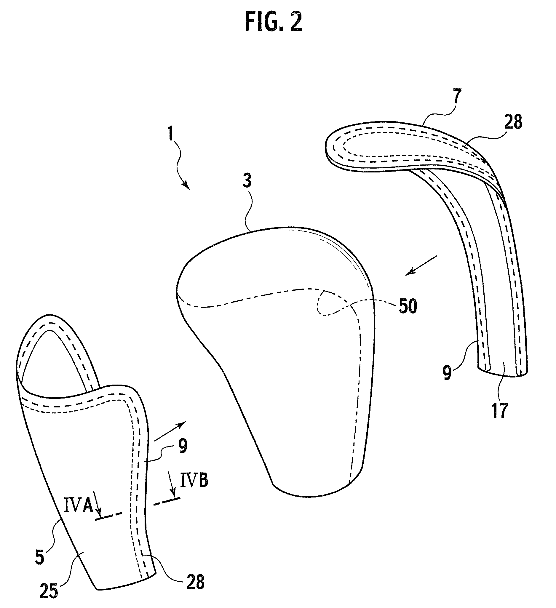
[0039]FIG. 1 is a figure showing a schematic configuration of a shift knob 1 according to the first embodiment of the present invention, and FIG. 2 is a figure showing a state in which the shift knob 1 is decomposed.

[0040]The shift knob 1 is to be used by being attached to a tip end portion of a change lever of a gearbox of a car or a tip end portion of an operation lever of a parking brake of a car, for example, and has a core member (body) 3 which constitutes a main body part, while the core member 3 is covered by a leather 5 and a leather 7. Note that the core member 3 is formed by the known technique. Namely, the core member 3 is integrally formed by a core metal and urethane resin by covering a core metal by a resin such as urethane resin.

[0041]To explain it in further detail, the core member 3 is covered by the leathers 5 and 7 as the back sides of the leathers 5 and 7 (faces on a side of a core member 3 and a side of a reticular layer to be described below of each of the leat...

second embodiment

[0124]FIG. 13 is a figure showing a schematic configuration of a steering wheel 101 according to the second embodiment of the present invention. Note that FIG. 13 is a figure in which the steering wheel 101 arranged in a car is viewed from a side of a driver.

[0125]FIG. 14 is a figure in which the steering wheel 101 is viewed from a back side (a side opposite to a driver).

[0126]The steering wheel 101 according to the second embodiment is covered by using the leather similar to the leather that covers the shift knob 1 according to the first embodiment, and has almost the same effects as the shift knob 1 according to the first embodiment.

[0127]To explain it in detail, the steering wheel 101 has a ring portion 105 and a spoke portion 107, while a main body part of the steering wheel 101 is constituted by a core member (body) 103.

[0128]Then, the core member 103 is covered by adhering a plurality of leathers (leathers which are separated from each other in a state before an arrangement on...


PUM

PropertyMeasurementUnit
widthaaaaaaaaaa
widthaaaaaaaaaa
thicknessaaaaaaaaaa

Abstract

In a leather 5 for covering a shift knob 1, it has a folded portion 9 formed by folding a leather material 20 such that back sides of the leather material 20 are set in contact with each other, at a small rigidity portion at which a flexural rigidity is small and which is formed along an edge 21 of the leather material 20.

Description

TECHNICAL FIELD[0001]The present invention relates to a leather, and more particularly to one in which a folded portion is formed at an edge section.BACKGROUND ART[0002]FIG. 19 is a Perspective view showing a schematic configuration of a conventional leather 200.[0003]The conventional leather 200 is used for covering a steering wheel, for example, and has a folded portion 202. This folded portion 202 is formed by forming a thin flesh portion 208 of a prescribed width on a side of an edge 206 of a leather material 204, sewing this thin flesh portion 208 with stitches (not shown), and folding and adhering the thin flesh portion 208 at a section (folding line) 210 of a constant distance (a half of a width of the thin flesh portion 208, for example) from the edge 206 (see Japanese Patent Application Laid Open No. H6-64546, for example).[0004]Then, the leather 200 with the folded portion 202 formed thereon is adhered to a core member of the steering wheel to cover a surface of the core m...

Claims


Application Information

Patent Timeline
Patent Type & Authority Applications(United States)
IPC IPC(8): G05G1/00B62D1/04G05G1/10G05G1/06B32B3/04
CPCB62D1/06B68F1/00Y10T74/20876Y10T428/2419Y10T74/2087
Inventor ARIMA, TAKASHIKOBAYASHI, SEIICHISUZUKI, TOMOYUKI
Owner MIDORI ANZEN
Why Eureka
Try Eureka