Manifold solenoid valve

Inactive Publication Date: 2009-08-27
KOGANEI
View PDF6 Cites 13 Cited by
  • Summary
  • Abstract
  • Description
  • Claims
  • Application Information

AI Technical Summary

Benefits of technology

[0015]According to the manifold solenoid valve of the present invention, by adding on the external pilot block to the internal pilot type manifold solenoid valve, the communication between the main flow path and the pilot air-supply flow path is shut off, and the manifold solenoid valve can be set to the external pilot type of supplying the pilot pressure directly to the pilot air-supply flow path from the outside via the external pilot flow path. Accordingly, by adding on the external pilot block to the internal pilot type manifold solenoid valve, the manifold solenoid valve can be easily set to the external pilot type. As mentioned above, by using the internal pilot type as a standard specification and

Problems solved by technology

Accordingly, it becomes complicated to manufacture

Method used


Image

  • Manifold solenoid valve
  • Manifold solenoid valve
  • Manifold solenoid valve

Examples


Example

[0037]Hereinafter, embodiments according to the present invention will be detailed based on the accompanying drawings.

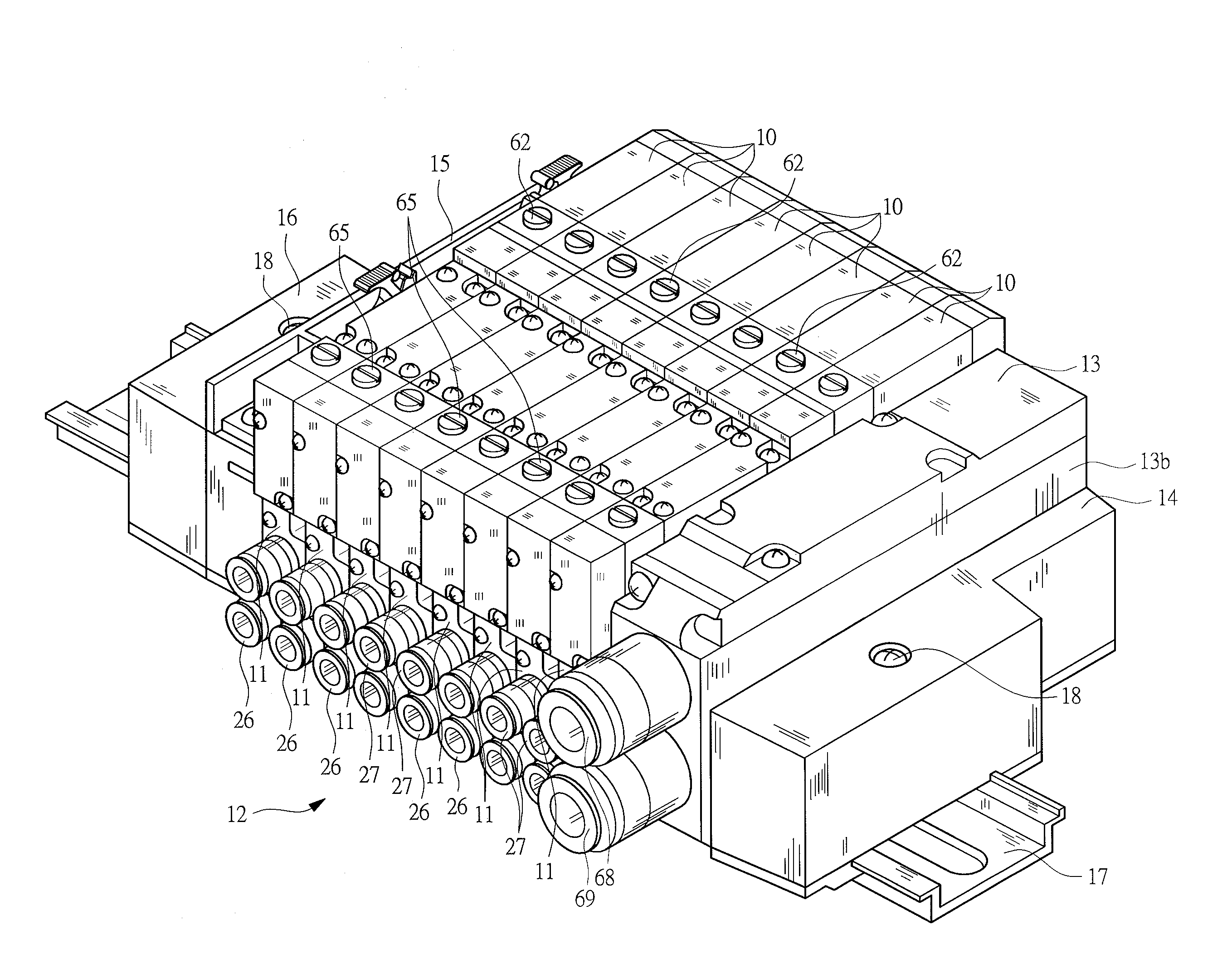
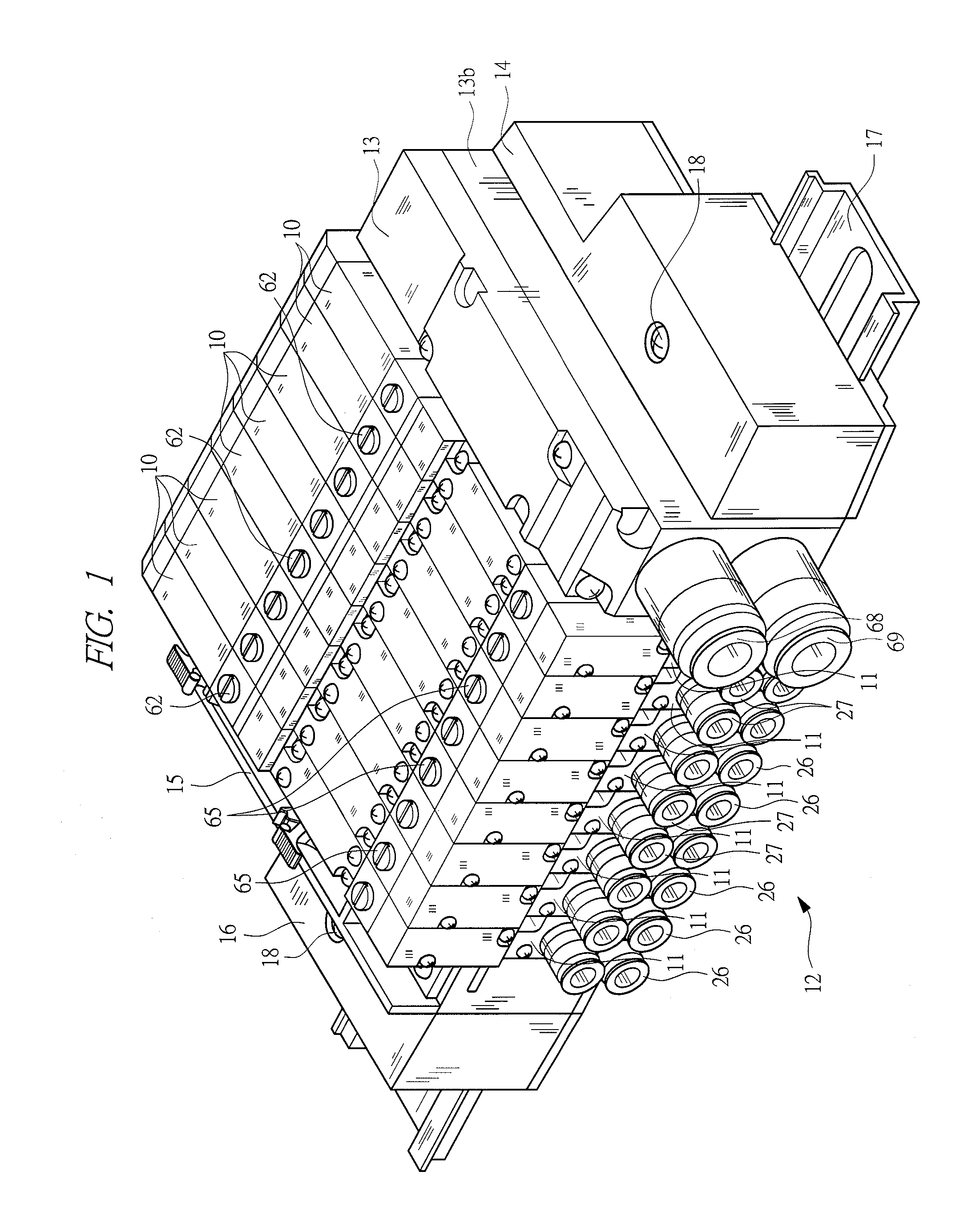
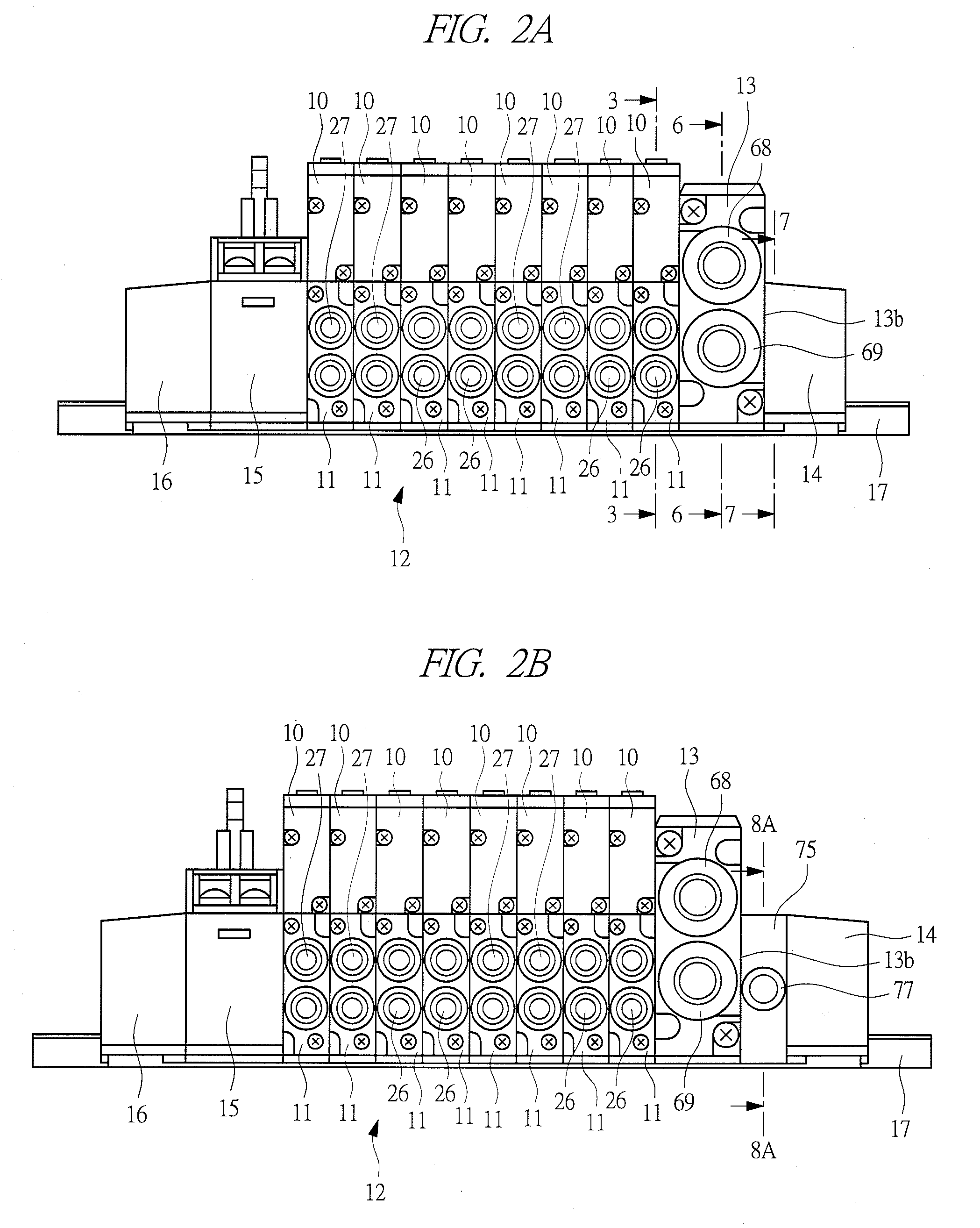
[0038]This manifold solenoid valve includes, as shown in FIGS. 1 and 2A, a plurality of valve assemblies 10, and base modules 11 to which the respective valve assemblies 10 are connected. One set of base 12 is formed by connecting the base modules 11, and the base 12 in the manifold solenoid valve is a divided type. The illustrated manifold solenoid valve has eight valve assemblies 10, but the manifold solenoid valve having any number of valve assemblies 10 may be used.

[0039]An air supply block 13 is connected to (struck to and mounted on) one end surface (right end surface in FIG. 2) of the base 12, and an end block 14 is connected to an outer surface of the air supply block 13. A wiring block 15 is connected to (mounted on) the other end surface of the base 12, and an end block 16 is connected to an outer surface of the wiring block 15. The base 12, and the air sup...


PUM


Abstract

A plurality of valve assemblies are provided to a base, and an air-supply flow path for supplying compressed air to each valve assembly is formed in the base. A main flow path communicating with the air-supply flow path and communicating with a pilot air-supply flow path is formed in an air supply block. When the compressed air is supplied to the air-supply flow path and the pilot air-supply flow path from the main flow path, a manifold solenoid valve becomes an internal pilot type. An external pilot flow path communicating with the pilot air-supply flow path is formed in an external pilot block, and when the external pilot block is provided, communication between the main flow path and the pilot air-supply flow path is shut off, and the manifold solenoid valve becomes an external pilot type in which the pilot pressure is supplied from the external pilot flow path.

Description

CROSS-REFERENCE TO RELATED APPLICATIONS[0001]Applicant hereby claims foreign priority benefits under U.S.C. §119 from Japanese Patent Application No. 2008-44490 filed on Feb. 26, 2008, the contents of which are incorporated by reference herein.TECHNICAL FIELD OF THE INVENTION[0002]The present invention relates to a manifold solenoid valve in which a plurality of valve assemblies each having a pilot solenoid valve are arranged in a base, and particularly to a manifold solenoid valve which can be set to any of an internal pilot type and an external pilot type.BACKGROUND OF THE INVENTION[0003]When a plurality of solenoid valves are collectively attached to a manifold for use, a manifold solenoid valve is used. The “manifold” is also called a “manifold base” or simply a “base”. The base is provided with a common air-supply flow path for supplying compressed air to each solenoid valve, and a common exhaust flow path for exhausting, to the outside, the compressed air that has been exhaust...

Claims


Application Information

Patent Timeline
IPC IPC(8): F16K31/02
CPCF15B13/0839F16K31/426F16K27/003Y10T137/5283Y10T137/87885Y10T137/86614
Inventor INABA, JOUJIOKAMOTO, KAZUYA
Owner KOGANEI
Why Eureka
Try Eureka