Illumination control system

a control system and lighting technology, applied in lighting devices, instruments, light sources, etc., can solve the problems of difficult to have a degree of freedom related to system setup, and it is difficult to set only a part of the lighting apparatus as a target to be controlled, and achieve accurate counting for each lighting apparatus. , the effect of high precision

Inactive Publication Date: 2009-08-27
MATSUSHITA ELECTRIC WORKS LTD
View PDF5 Cites 76 Cited by
  • Summary
  • Abstract
  • Description
  • Claims
  • Application Information

AI Technical Summary

Benefits of technology

[0004]In view of the above, the present invention provides an illumination control system, capable of controlling lighting apparatuses based on various kinds of detection information relative to ambient environments of the lighting apparatuses, performing the illumination control so as to be more suitable for the ambient environments of the lighting apparatuses in comparison with conventional illumination control performed based on only one kind of detection information, and increasing a degree of freedom related to system setup.
[0007]In such configuration, each lighting apparatus includes a unit attaching part to which one of functional units of various kinds for detecting a change in an ambient environment thereof can be attached, and by attaching the functional units to the unit attaching parts, the lighting apparatuses can be controlled based on various kinds of detection information. Therefore, in comparison with conventional illumination control carried out based on only one specific kind of detection information, the illumination control in accordance with the embodiment of the present invention can be carried out in a manner more suitable for the ambient environments of the lighting apparatuses. Further, each lighting apparatus can be set to belong to one or more of the plural groups corresponding to the plural kinds of the functional units, each group being operated based on information detected by a corresponding functional unit, so that the degree of freedom related to system setup can be increased.
[0011]For this reason, when the lighting apparatus carries out the feed-back control on the lamp thereof based on the detected brightness information, errors can be prevented from occurring due to a variation in the brightness caused by the illumination level changed of the human detection control. Thus, precise lamp control can be made in the brightness detection control group.
[0013]The timer of each lighting apparatus can count the accumulative turn-on time of the lamp and the accumulative turn-on time of the lamp can be reset to zero when the lamp is replaced. Therefore, the accumulative turn-on time of the lamp can be accurately counted for each lighting apparatus. Thus, based on the accurately counted accumulative turn-on time, the luminous flux can be maintained to be kept at a constant value despite of reduction of the luminous flux due to a characteristic of the lamp with the lapse of time, so that the luminous flux of the lamp can be adjusted to be maintained at a desired value with high precision.

Problems solved by technology

H8-250285, no information about whether to control the lighting apparatuses individually or collectively is disclosed, and it is not possible to set only a part of the lighting apparatuses as a target to be controlled.
As such, it is difficult to have a degree of freedom related to system setup.

Method used


Image

  • Illumination control system
  • Illumination control system
  • Illumination control system

Examples


first embodiment

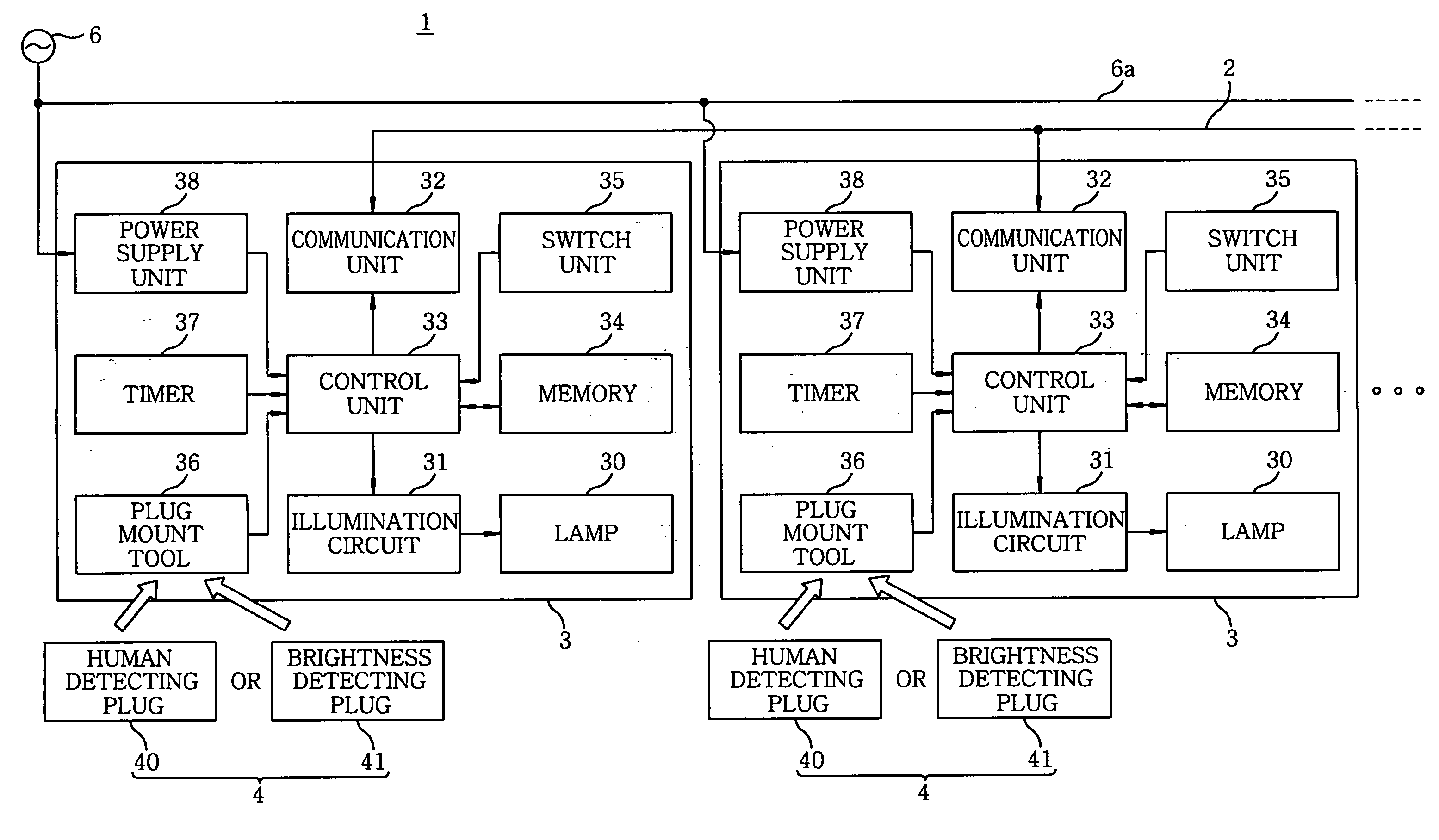
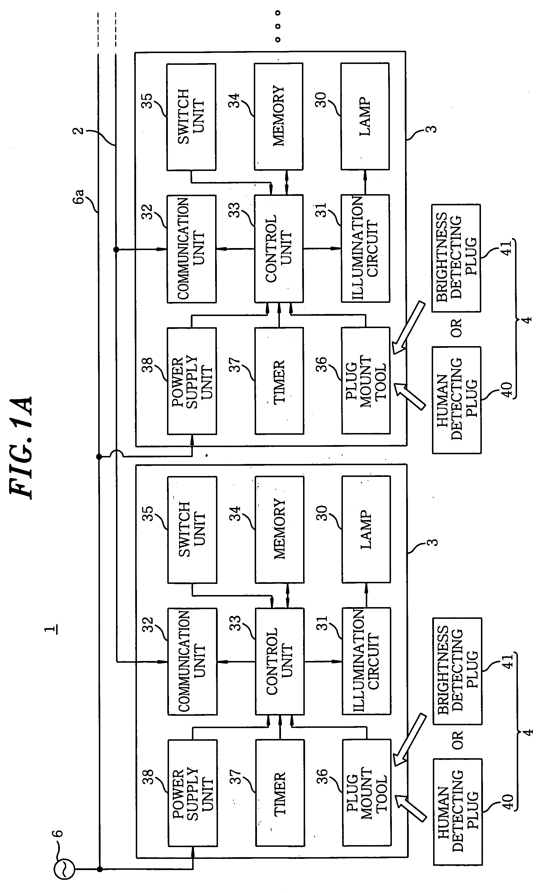
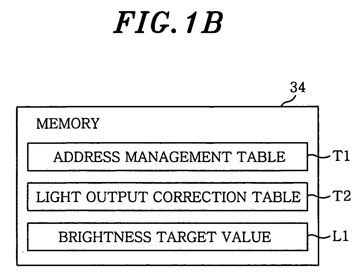
[0024]FIGS. 1A and 1B show configurations of the illumination control system in accordance with a first embodiment of the present invention and various data stored in the memories of lighting apparatuses of the illumination control system. The illumination control system 1 includes a plurality of lighting apparatuses 3 each connected to a communications line 2, and a number of functional plugs (functional units) 4 of plural kinds which function to detect information from ambient environments of the lighting apparatuses 3 and detachably attached to the lighting apparatuses 3. The respective lighting apparatuses 3 are operated based on various kinds of information detected by the functional plugs 4. A functional plug 4 includes a human detecting plug 40 which functions to detect a human being or a brightness detecting plug 41 which functions to detect brightness.

[0025]As shown in FIG. 2, the lighting apparatuses 3 (3A to 3E) each belongs to one or more of the plural groups correspondi...

second embodiment

[0052]Components of the illumination control system in accordance with a second embodiment of the present invention are almost identical to those of the first embodiment, and thus will be described with reference to FIG. 1. In the second embodiment, the illumination control system 1 is configured so that at least one lighting apparatus 3, e.g., the lighting apparatus 3A shown in FIG. 6, is set to belong to both of the human detection control group 50 and a brightness detection control group 51 and the brightness detecting plug 41 is attached to the lighting apparatus 3A.

[0053]In this embodiment, the lighting apparatuses 3B to 3I have the same configuration as those of the first embodiment, and redundant description thereof will be omitted. That is, illumination levels of the lighting apparatuses 3D and 3E belonging to the brightness detection control group 51 are controlled by the brightness information detected by the brightness detecting plug 41 attached to the lighting apparatus ...


PUM


Abstract

An illumination control system includes lighting apparatuses connected to a communications line and a number of functional units of plural kinds functioning to detect information from ambient environments of the lighting apparatuses. Each lighting apparatus includes a lamp, an illumination circuit, a communication unit, a control unit, and a unit attaching part to which the functional unit is detachably attached. Each lighting apparatus belongs to one or more of plural groups corresponding to the functional units, the groups being operated based on information detected by the respective functional units. A functional unit having a detecting function corresponding to an operation of each group is attached to each unit attaching part of at least one lighting apparatus of each group, and each communication unit of the at least one lighting apparatus sends the control signal including information detected by the corresponding functional unit to another lighting apparatus in the same group.

Description

FIELD OF THE INVENTION[0001]The present invention relates to an illumination control system that controls illumination of lighting apparatuses provided in the system.BACKGROUND OF THE INVENTION[0002]Conventionally, there is known an illumination control system that includes a plurality of lighting apparatuses, an illuminance detecting unit for detecting illuminance on surroundings provided by the lighting apparatuses, and a control unit for turn-on control of the lighting apparatuses based on data inputted from the illuminance detecting unit at regular intervals (see, e.g., Japanese Patent Laid-open Application No. H8-250285). In such illumination control systems, the control unit controls the turn-on state of the lighting apparatuses such that the average illuminance on a surface illuminated is kept almost constant regardless of time.[0003]However, in the conventional technique described in the Japanese Patent Laid-open Application No. H8-250285, the lighting apparatuses are contro...

Claims


Application Information

Patent Timeline
Patent Type & Authority Applications(United States)
IPC IPC(8): H05B37/02
CPCH05B37/0218Y02B20/46H05B37/0254H05B37/0227H05B47/11H05B47/115H05B47/18Y02B20/40
Inventor KAWASHIMA, TOSHIKAZUKATOU, JUNICHINANAHARA, ATSUO
Owner MATSUSHITA ELECTRIC WORKS LTD
Why Eureka
Try Eureka