In-Circuit Testing For Integrity Of Solid-State Switches

a solid-state switch and integrity testing technology, applied in electronic switching, pulse technique, instruments, etc., can solve problems such as failure to detect a shorted solid-state power switch, inability to accept power switching applications, and failure to use solid-state power switches as power control devices

Active Publication Date: 2009-08-27
ASTRONICS ADVANCED ELECTRONICS SYST
View PDF13 Cites 49 Cited by
  • Summary
  • Abstract
  • Description
  • Claims
  • Application Information

AI Technical Summary

Benefits of technology

[0030]The present invention provides methods and apparatuses that provide for testing of power switches without requiring destructive elements such as fuses, and that allow switch integrity testing before power activation and during operation.

Problems solved by technology

Solid state power switches used as power control devices tend to fail in shorted states, which is often unacceptable in power switching applications.
This method is not failsafe, since there is no way to know if one of the switches has failed closed.
Therefore, this technique fails to detect a shorted solid state power switch where the power switch is shorted but the load is not.
However, this technique must be carefully adapted for different size loads and does not provide user-resettable capabilities.
The current techniques, however, do not provide a fault detection and switching circuit and method of operation for use with a power control device to detect an abnormal open or abnormal closed state in the power control device.
If the test does not complete successfully, the signal is lost.
If the switch is determined as improperly closed (conducting), the control circuitry diverts energy delivered to the load through fuse circuitry, thereby blowing a fuse and decoupling the load from the power source.
When an integration based on a comparison of actual voltage of a source and a reference voltage exceeds a predetermined value, the source is considered unreliable.
Failure of a power switch can lead to hazardous conditions, and so the ability to monitor power switching systems and detect faults can be especially important in aircraft applications.

Method used


Image

  • In-Circuit Testing For Integrity Of Solid-State Switches
  • In-Circuit Testing For Integrity Of Solid-State Switches
  • In-Circuit Testing For Integrity Of Solid-State Switches

Examples


Embodiment Construction

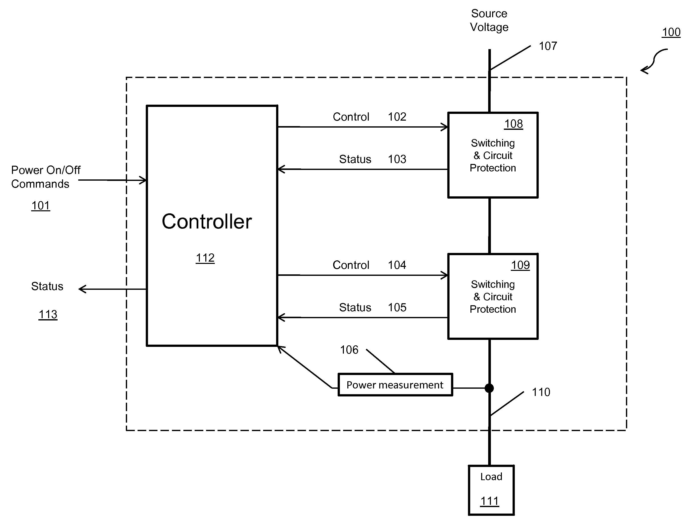
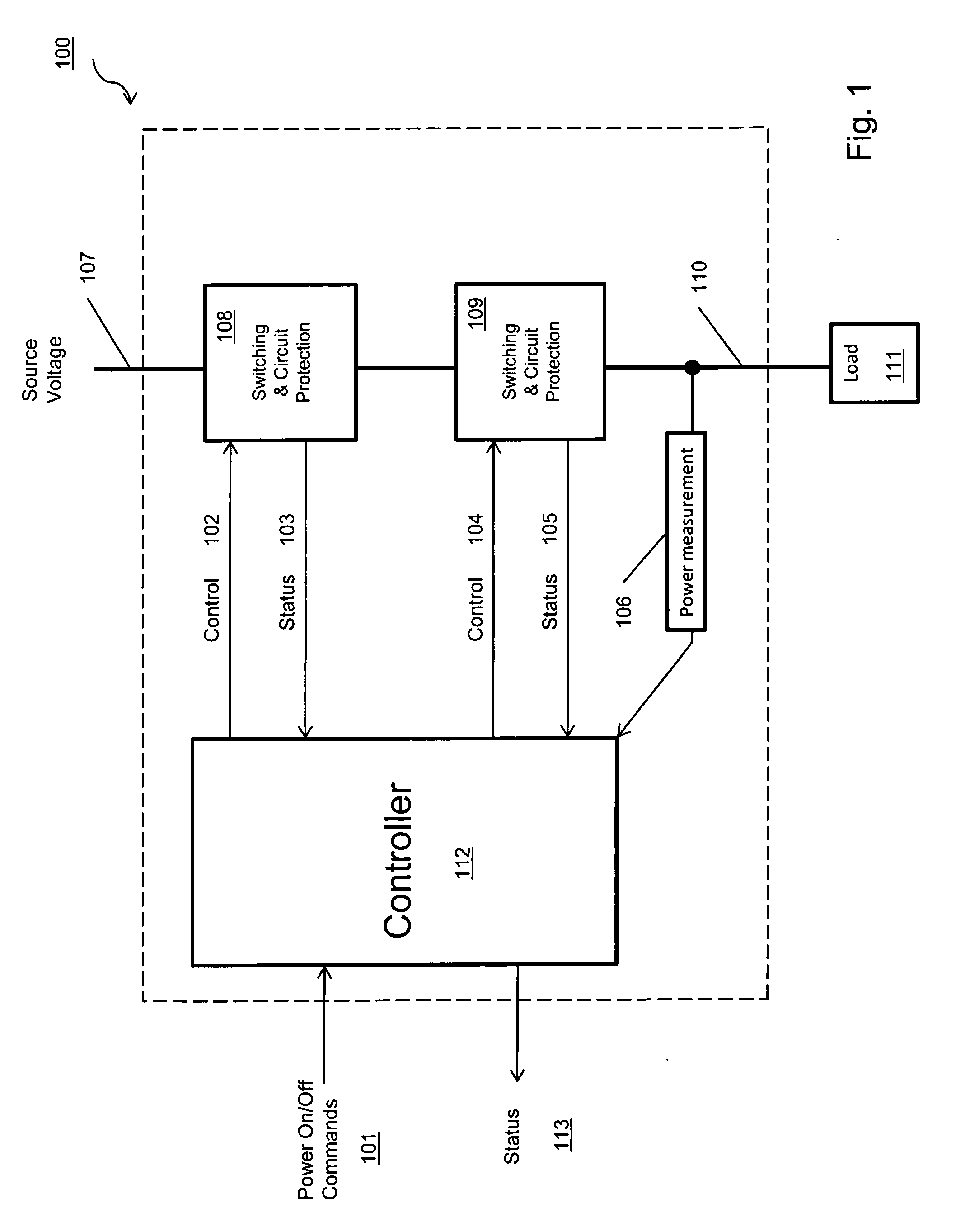
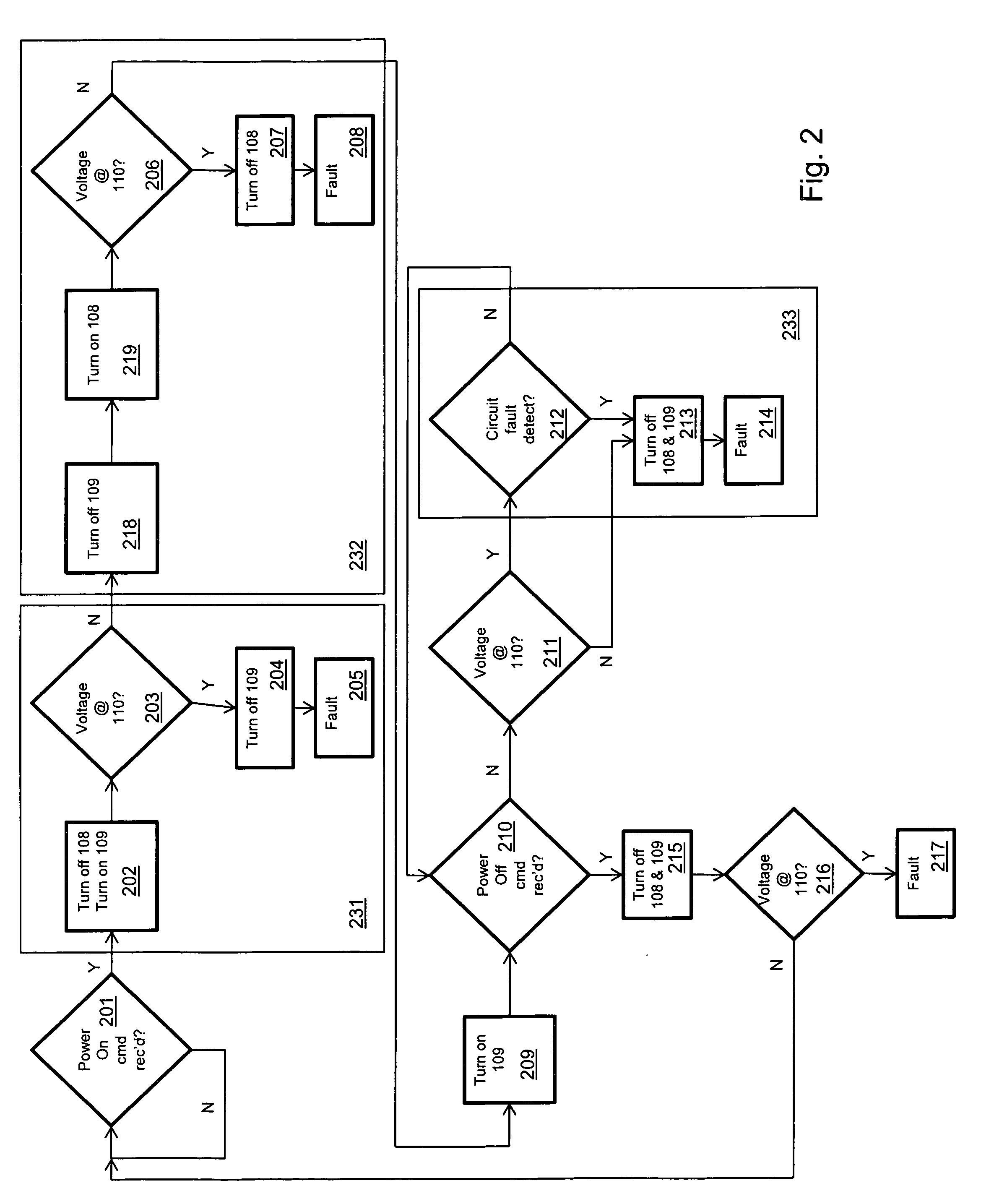
[0043]The present invention provides methods and apparatuses that provide for testing of power switches without requiring destructive elements such as fuses, and that allow switch integrity testing before power activation and during operation.

[0044]An example embodiment of the present invention comprises a method of testing first and second switches, wherein the first switch has first and second terminals and a control input, and wherein the second switch has first and second terminals and a control input, and wherein the second terminal of the first switch is in communication with the first terminal of the second switch, and wherein the first terminal of the first switch is adapted to be placed in communication with a power supply, and wherein the second terminal of the second switch is adapted to be placed in communication with a load, using a controller that is in communication with the control input of the first switch and the control input of the second switch, comprising the f...


PUM


Abstract

A switching and fault detection circuit comprises two controllable switches capable of coupling a power source to a load. A controller can control the switches and test them for faults, and a voltage sensor can read the output voltage going to the load. Dual-redundant switches and fault detection circuitry can provide correct operation if one should fail. Control and feedback logic can determine if each of the solid-state switches is operating correctly during the power-on and power-off cycles and can also check for a fail-open condition during normal operations. If it is determined that a solid switch has failed open or closed, a fault can be generated.

Description

FIELD OF THE INVENTION[0001]The present invention relates to a fault detection and switching circuit for use with a power control device to detect an abnormal open or abnormal closed state in the power control device, and is useful in applications such as facilitating safe aircraft control.BACKGROUND[0002]Solid state power switches used as power control devices tend to fail in shorted states, which is often unacceptable in power switching applications. Various fault detection circuits for detecting such short circuits in power switching applications are known. In one such technique, a second solid state power switch device is used to turn off the current when a primary solid state power switch fails to respond. This method is not failsafe, since there is no way to know if one of the switches has failed closed.[0003]In another technique, a mechanical fuse or circuit breaker is added in series with the solid state power switch device. This technique is based on the assumption that whe...

Claims


Application Information

Patent Timeline
Patent Type & Authority Applications(United States)
IPC IPC(8): G08B21/00
CPCH03K17/18G01R31/3277
Inventor AUSMAN, MARCDEVRIES, KEVINDOSTAL, JAKE
Owner ASTRONICS ADVANCED ELECTRONICS SYST
Why Eureka
Try Eureka