

Broad-Area Microlasers and Methods for Driving Them
a microlaser and wide-area technology, applied in the direction of laser details, semiconductor lasers, electrical apparatus, etc., can solve the problems of reducing the degree of spatial coheren
- Summary
- Abstract
- Description
- Claims
- Application Information
AI Technical Summary
Benefits of technology
Problems solved by technology
Method used
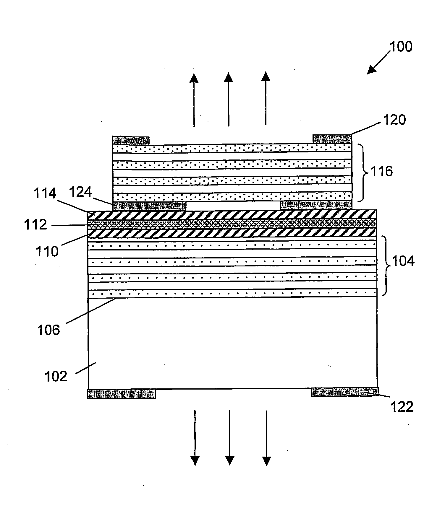
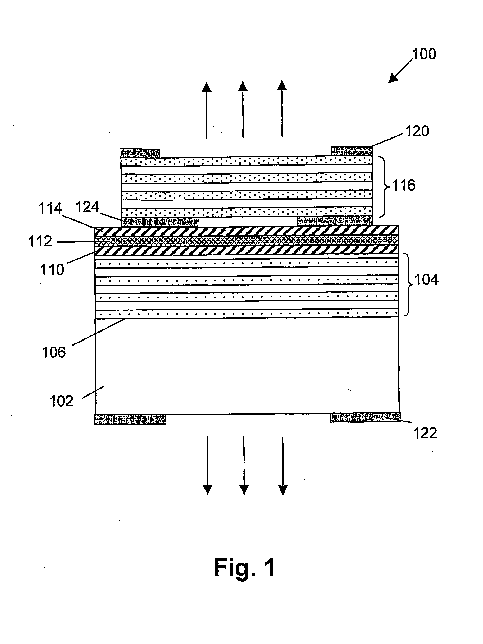
Image

Examples
first embodiment
[0036]the present invention, describes a multi-mode VCSEL and a method for driving the multi-mode VCSEL. The method for driving the multi-mode VCSEL and the multi-mode VCSEL adapted to be driven accordingly, allows to obtain a Gaussian far-field pattern for the multi-mode VCSEL, without the need for additional active or passive intra- or extra cavity elements. The method comprises modulating the electric driving current sent through a multi-mode VCSEL in such a way that a significant reduction of the spatial coherence in the light beam of the multi-mode VCSEL occurs. With significant reduction of the spatial coherence in the light beam of the multi-mode VCSEL, it is meant that the light beam is not completely coherent over its transverse profile, or in other words that the illumination beam has a coherence area smaller than the aperture area, more preferably smaller than one quarter of the aperture area, even more preferably smaller than one tenth of the aperture area, still more pr...
fourth embodiment
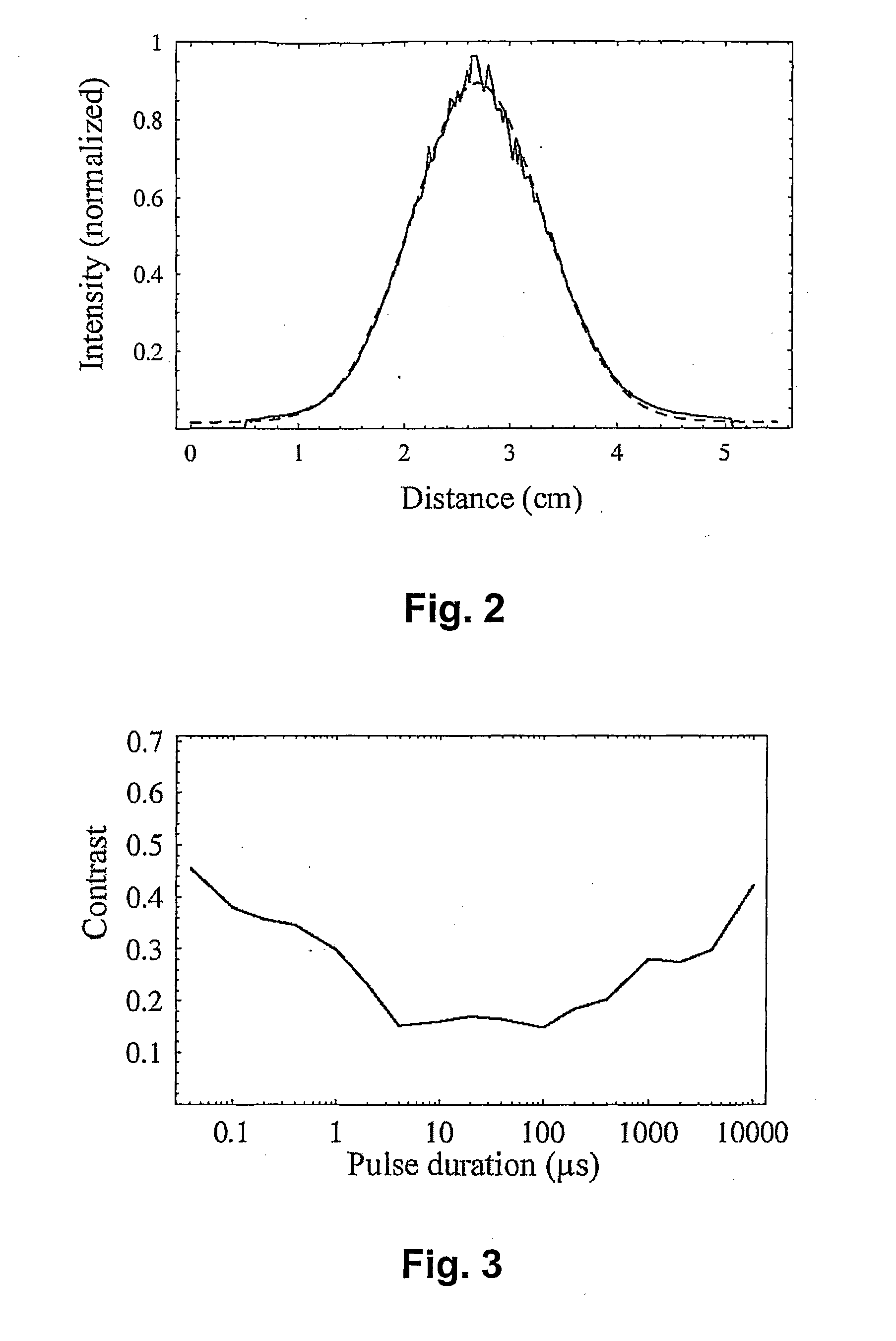
[0040]In a fourth embodiment, the invention relates to a broad area VCSEL, a corresponding driver and a method for driving a broad area VCSEL as described in any of the previous embodiments, wherein the electric driving current I(t) sent through the multi-mode VCSEL is a rectangular pulse driving current with a pulse height ph and a pulse duration pd as shown in FIG. 6. The rectangular pulse driving current is selected such that a reduction of the spatial coherence in the light beam of the multi-mode VCSEL occurs. The boundary conditions for the driving current allowing a sufficient reduction of the spatial coherence area, can for a rectangular pulse driving current be expressed as boundary conditions for the pulse height ph and the pulse duration pd.
[0041]By way of example, a selection of driving conditions based on experimental results and a selection of driving conditions based on modelling results are determined for an oxide-confined multi-mode VCSEL driven by a rectangular puls...
third embodiment
[0042]Based on experimental results for a series of Young's experiments, as described in more detail in the third embodiment, an allowable set of driving conditions is defined by the pulse duration being selected from a range with a lower limit of 0.1 μs, preferably 0.5 μs, more preferably 1 μs still more preferably 2 μs and an upper limit of 5000 μs, preferably 1000 μs, more preferably 500 μs, still more preferably 100 μs and the pulse height ph being selected larger than 30 mA, preferably larger than 75 mA, more preferably larger than 100 mA. A more optimised set of driving conditions can be obtained if one of the driving current parameters is selected and the remaining driving parameter is selected accordingly based on the equations
ph>60 mA
Pd−5.36 μs.exp(−0.032*Ph / mA)>0
Pd−7200 μs.exp(−0.026*Ph / mA)<0 [5]
determined from the experimental results shown in FIG. 5.
PUM
 Abstract
Description
Claims
Application Information