Interface Device and Protocol

a technology of interface device and protocol, which is applied in the field of injector and imaging equipment, can solve the problems of exposing a patient to a determined amount of energy, synchronizing between the devices is difficult, and starting the imaging equipment too early or too la

Active Publication Date: 2009-08-27
ACIST MEDICAL SYST
View PDF28 Cites 22 Cited by
  • Summary
  • Abstract
  • Description
  • Claims
  • Application Information

AI Technical Summary

Benefits of technology

[0006]In one alternative embodiment, the present invention is directed to an interface device and system for establishing an operating interface between an injector device and diagnostic imaging equipment. In one alternative embodiment, the interface device may permit an operator to concurrently operate and control both the injector devic...

Problems solved by technology

The imaging equipment may expose a patient to a determined amount of energy after injection of the fluid.
The use of separate interfaces for both the injector and the imaging equipment may make synchronization between the devices difficult.
There may be situations where the lack of synchronization may result in starting the imaging equip...

Method used


Image

  • Interface Device and Protocol
  • Interface Device and Protocol
  • Interface Device and Protocol

Examples


Embodiment Construction

[0023]The present invention now will be described hereinafter with reference to the accompanying drawings. The invention may be embodied in many different forms and the drawings and descriptions herein should not be construed as limited to the embodiments set forth herein. Like numbers refer to like elements throughout.

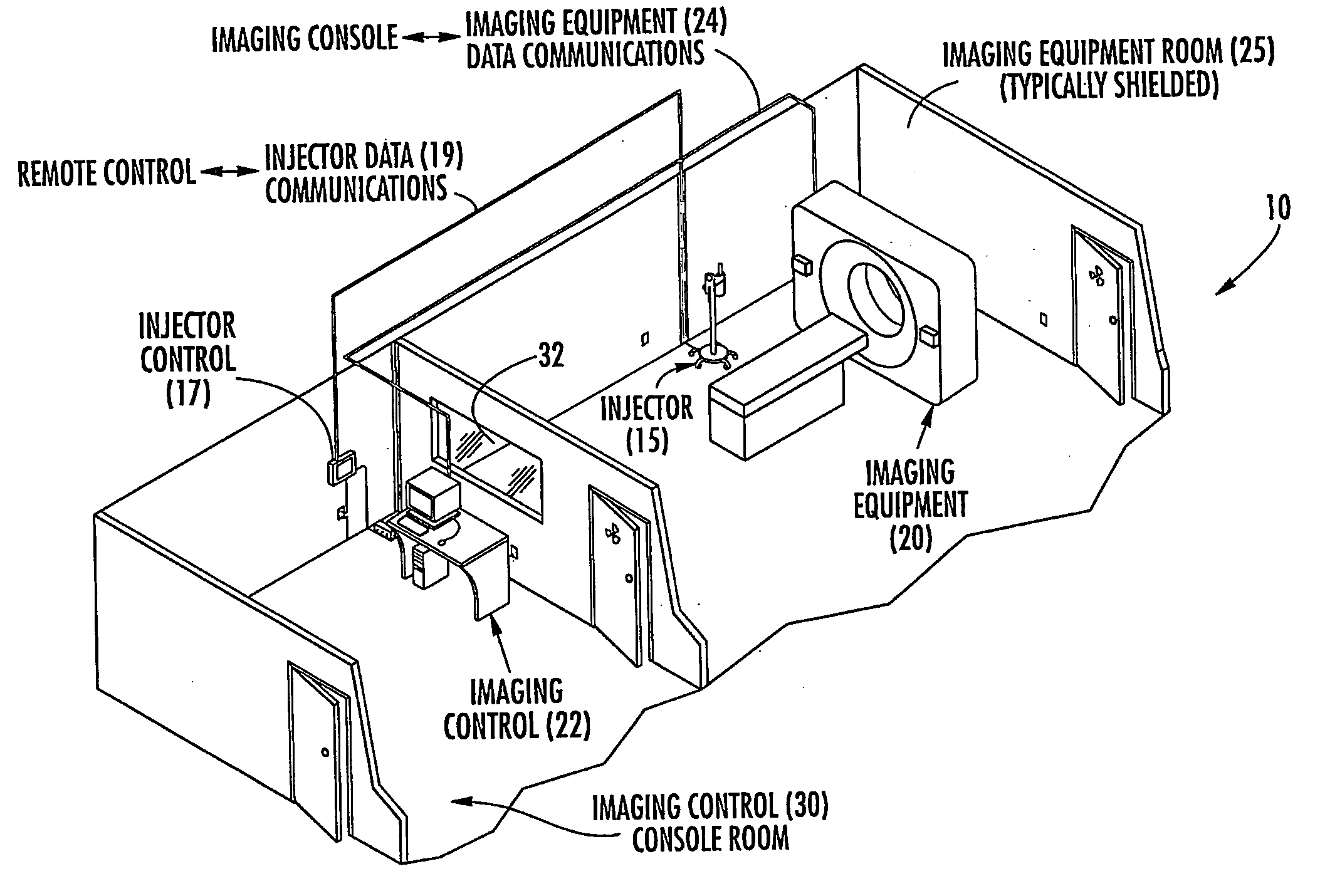
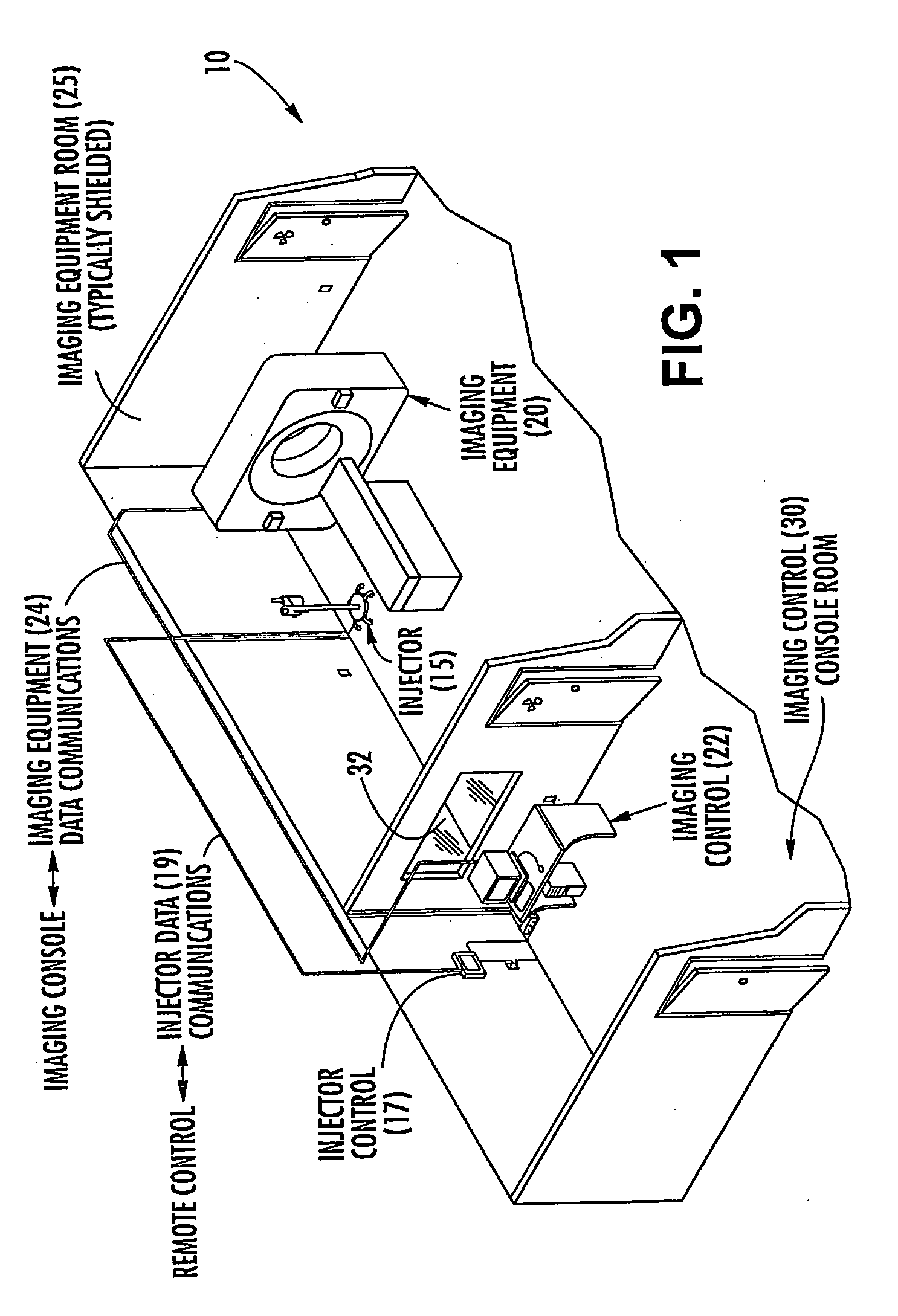
[0024]With reference to the drawings, FIG. 1 generally illustrates a conventional computed tomography (CT) imaging system arrangement located in an imaging suite 10 The CT imaging system typically includes a powered CT injector 15 and CT imaging equipment 20 (“scanner”) that are both normally located in an imaging room 25. The CT injector 15 and CT scanner 20 are usually both separately controlled by different remote consoles 17, 22, respectively. The remote consoles 17, 22 may be located externally of the imaging room in a separate control room 30. As shown, the imaging suite may include a viewing window 32 through which the operator may view the procedure. The imagi...


PUM


Abstract

The invention is an interface device and system for establishing an operating interface between an injector device and diagnostic imaging equipment. In one embodiment, the interface device may permit an operator to concurrently operate and control the injector device and the imaging equipment. The interface device may permit the injector system and the imaging system to communicate information regarding their current and future operational status with each other. The interface device may be used to synchronize the operation of the imaging equipment and the injector device. In one embodiment, the injector device and the imaging equipment may be able to communicate with each other directly or through the interface device via a communications protocol comprising binary logic signals. The binary logic signals may comprise one or more of a low strength signal, a high strength signal, an oscillating signal that oscillates between low and high signal strength, and combinations thereof.

Description

BACKGROUND OF THE INVENTION[0001]The invention relates generally to injector and imaging equipment for performing diagnostic imaging on a patient, and more particularly to an interface device for facilitating communication between an injector device and imaging equipment.[0002]In many medical diagnostic procedures, a physician or other person injects a patient with a fluid, such as a contrast media, that is detectable with diagnostic imaging equipment. In recent years, a number of injector-actuated syringes and powered injectors for pressurized injection of fluids have been developed for use in diagnostic imaging procedures such as angiography, computed tomography, ultrasound, and NMR / MRI. In general, the powered injectors and imaging equipment may be monitored and operated with separate interfaces.[0003]The imaging equipment may expose a patient to a determined amount of energy after injection of the fluid. In many circumstances it may be desirable to synchronize the timing of the ...

Claims


Application Information

Patent Timeline
IPC IPC(8): G06K9/00A61M5/00A61M5/172G16Z99/00
CPCA61B6/481A61B6/504A61B6/566A61B6/548A61M5/172A61M2205/3561G06F19/3406A61M5/007G16H40/63G16Z99/00
Inventor WILLIAMS, ROBERTCROSS-HANSEN, ALANTENGCO, TITO
Owner ACIST MEDICAL SYST
Why Eureka
Try Eureka