System for, and method of, accurately and rapidly determining, in real-time, true bearings of radio frequency identification (RFID) tags associated with items in a controlled area

a technology of radio frequency identification and real-time determination, applied in the field of real-time accurate and rapid determination of the true bearing of radio frequency identification (rfid) tags associated with items in the controlled area, can solve the problems of high degree of precision, difficult to accurately determine in practice, and practical limit on the number of antenna elements that can be used in each array

Active Publication Date: 2017-04-20
SYMBOL TECH LLC
View PDF0 Cites 20 Cited by
  • Summary
  • Abstract
  • Description
  • Claims
  • Application Information

AI Technical Summary

Problems solved by technology

As advantageous as such known inventory-taking RFID systems utilizing antenna arrays have been, it has proven difficult in practice to accurately determine, with a high degree of precision, the true bearing, i.e., the angular direction both in azimuth and elevation, of a particular tag, relative to a particular reader.
There is a practical limit on the number of antenna elements that can be used in each array.
It has also proven difficult in practice to rapidly determine the true bearing of a particular tag relative to a particular reader in real-time.
Depending on the size of the controlled area, it can take a significant amount of time, as well as multiple movements of the primary transmit beam and multiple samples of the RSS, to find the peak RSS of each tag and, hence, its tag bearing.
Determining the bearing, i.e., the angular direction both in azimuth and elevation, of each tag based on the peak RSS of the primary receive beam has not only been imprecise due to the aforementioned limit on the number of antenna elements and the relatively broad beam width, but also slow.
Bearing errors on the order of 5 to 10 degrees, lengthy latency delays, and limits on the number of tags that can be located and tracked in a given amount of time have been reported, and are not tolerable in many applications.

Method used


Image

  • System for, and method of, accurately and rapidly determining, in real-time, true bearings of radio frequency identification (RFID) tags associated with items in a controlled area
  • System for, and method of, accurately and rapidly determining, in real-time, true bearings of radio frequency identification (RFID) tags associated with items in a controlled area
  • System for, and method of, accurately and rapidly determining, in real-time, true bearings of radio frequency identification (RFID) tags associated with items in a controlled area

Examples


Embodiment Construction

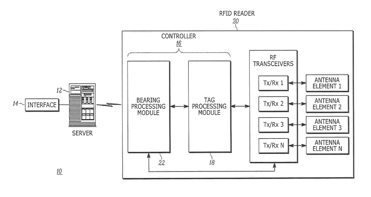
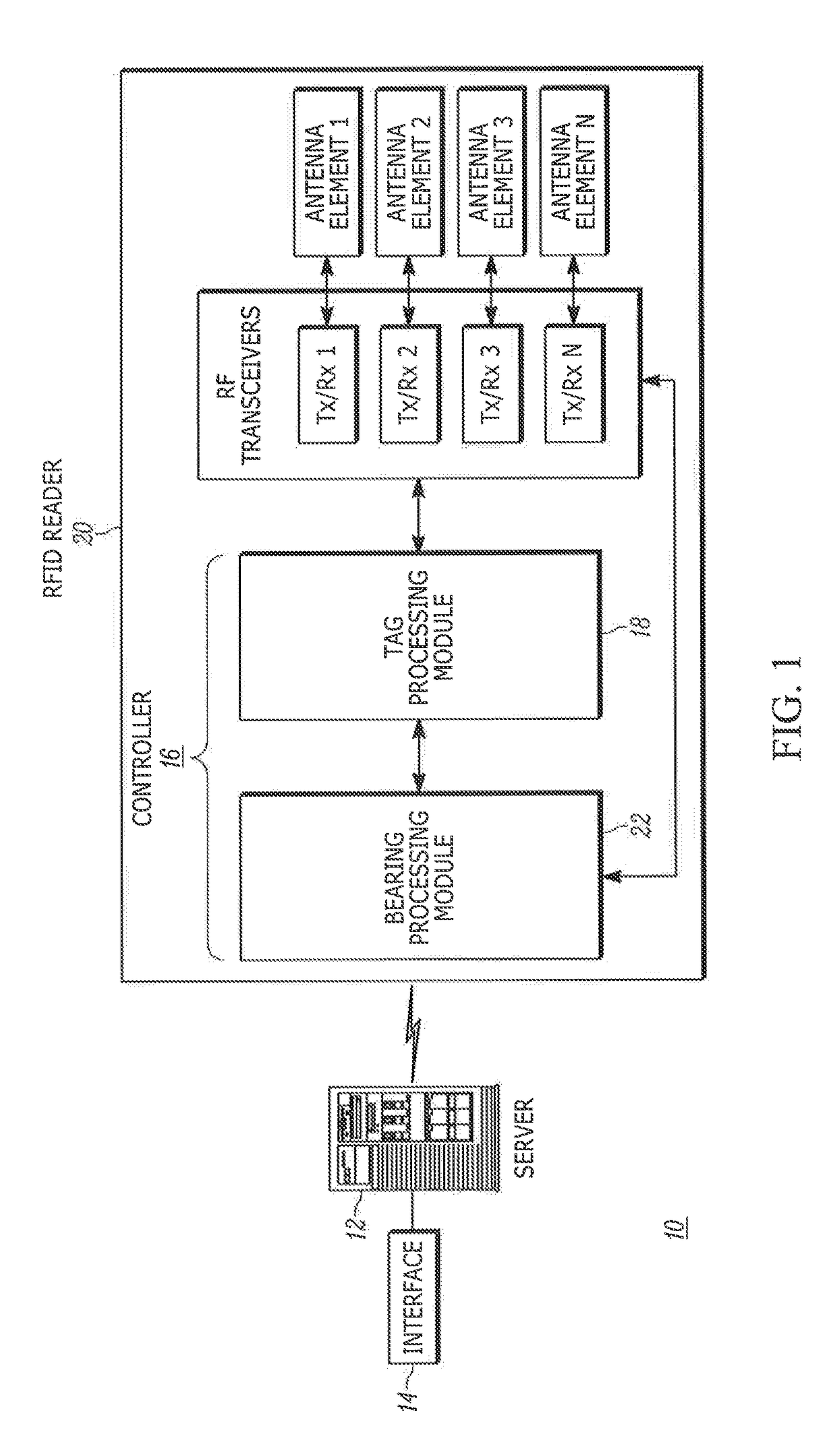
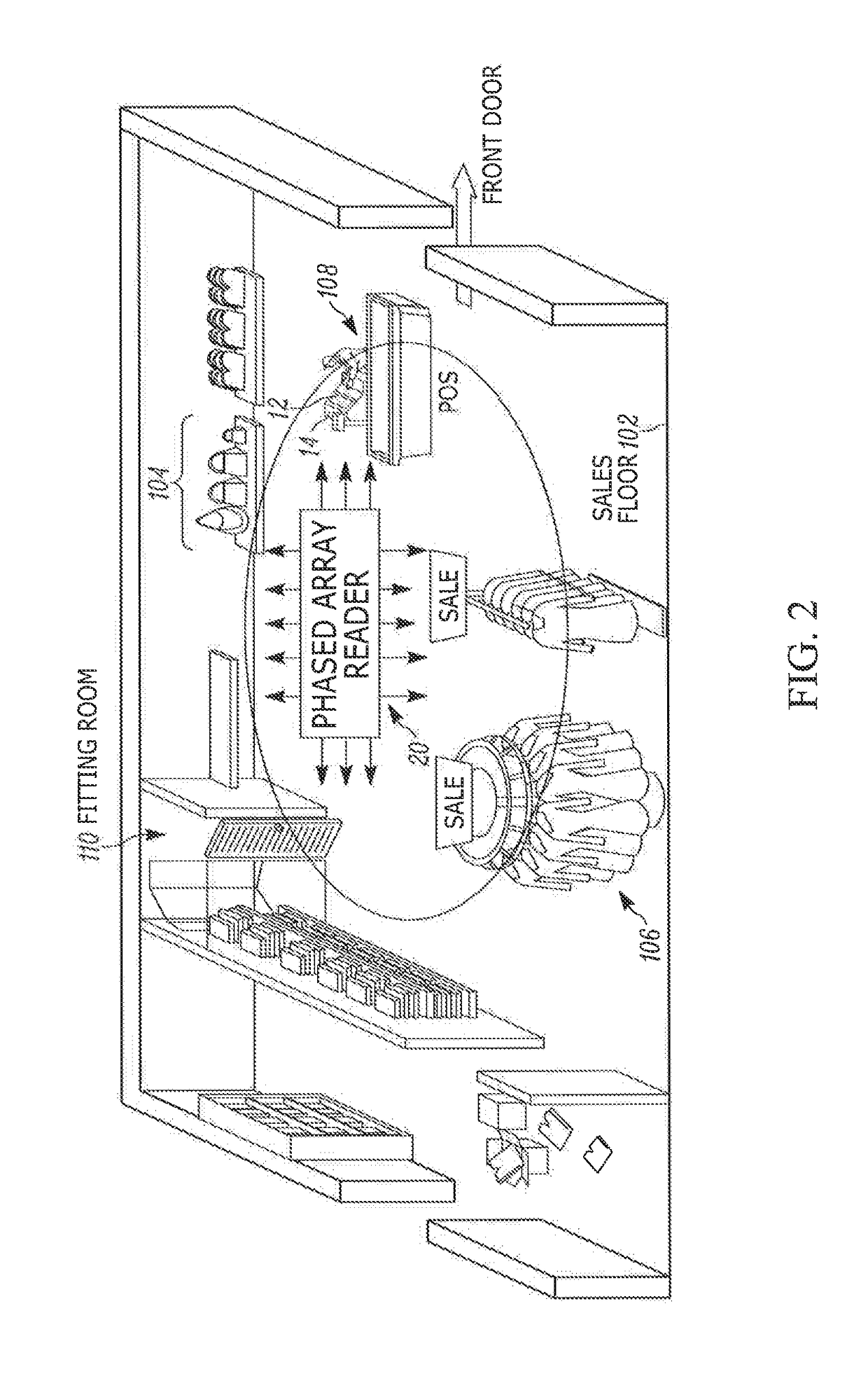
[0018]One aspect of this disclosure relates to a radio frequency (RF) identification (RFID) tag reading system for accurately and rapidly determining, in real-time, true bearings of RFID tags associated with items in a controlled area. The controlled area may be a retail store, a warehouse, or any other confined or open area in which RFID-tagged items are to be monitored. The controlled area may be indoors or outdoors, and may be a single sector or volume of space, or may be, and often is, subdivided into multiple sectors. The system includes an RFID reader having an array of antenna elements, e.g., a phased array; a plurality of RF transceivers; and a controller or programmed microprocessor operatively connected to the transceivers, and operative for controlling the transceivers.

[0019]The controller executes a tag processing module operative for steering a primary transmit beam over the controlled area by transmitting a primary transmit signal via the antenna elements to each tag, ...


PUM


Abstract

A radio frequency identification (RFID) tag reading system and method accurately and rapidly determine, in real-time, true bearings of RFID tags associated with items in a controlled area. Primary transmit and receive beams are steered over the area, and multiple secondary receive beams are substantially simultaneously steered to a plurality of bearings in the area. The highest signal strength of secondary receive signals from the secondary receive beams determines an approximate tag bearing of each tag. Two secondary receive beams at opposite sides of the approximate tag bearing in elevation are selected to obtain a pair of elevation offset signals, and two secondary receive beams at opposite sides of the approximate tag bearing in azimuth are selected to obtain a pair of azimuth offset signals. The elevation offset signals and the azimuth offset signals are processed to determine a true bearing for each tag in real-time.

Description

BACKGROUND OF THE INVENTION[0001]The present disclosure relates generally to a system for, and a method of, accurately and rapidly determining, in real-time, true bearings of radio frequency (RF) identification (RFID) tags associated with items in a controlled area, especially for locating and tracking the RFID-tagged items for inventory control.[0002]Radio frequency (RF) identification (RFID) technology is becoming increasingly important for logistics concerns, material handling and inventory management in retail stores, warehouses, distribution centers, buildings, and like controlled areas. An RFID system typically includes an RFID reader, also known as an RFID interrogator, and preferably a plurality of such readers distributed about a controlled area. Each RFID reader interrogates one or more RFID tags in its coverage range. Each RFID tag is usually attached to, or associated with, an individual item, or to a package for the item, or to a pallet or container for multiple items. ...

Claims


Application Information

Patent Timeline
Patent Type & Authority Applications(United States)
IPC IPC(8): G06K7/10G06Q10/08G06K19/077
CPCG06K7/10366G06K19/07794G01S2013/0245G01S13/751G06K7/10099G06Q10/087G06K7/10356H04N1/00
Inventor KOCH, MICHAEL J.SWOPE, CHARLES B.BEKRITSKY, BENJAMIN J.
Owner SYMBOL TECH LLC
Why Eureka
Try Eureka