Optical Crossbar Switch

a crossbar switch and optical technology, applied in the field of crossbar switches, can solve the problems of large volume of operating space, unwieldy equipment, complex task of efficiently managing the coupling and disconnection of large numbers of optic fiber ends without fibers becoming entangled in prior art crossbar switches, etc., and achieve the effect of small volume of space and efficient coupling managemen

Active Publication Date: 2009-08-27
WAVE2WAVE
View PDF8 Cites 25 Cited by
  • Summary
  • Abstract
  • Description
  • Claims
  • Application Information

AI Technical Summary

Benefits of technology

[0009]An aspect of some embodiments of the present invention relates to providing an improved optical crossbar switch that provides for efficient management of the coupling and uncoupling of relatively large numbers of optic fibers in a relatively small volume of space.
[0010]An aspect of some embodiments of the invention relates to providing an optical crossbar switch wherein large numbers of optic fibers may be coupled and uncoupled without the fibers becoming entangled.
[0019]In some embodiments of the invention, the socket functions to aid alignment of the switch ends. In some embodiments of the invention, the socket alternatively or additionally provides mechanical support for the coupled switch ends. Optionally, the socket provides mechanical support for the fiber-end carriages to which the switch ends are mounted and mechanically supports the carriages in positions that maintain the switch ends optically coupled.
[0020]In accordance with an embodiment of the invention, the crossbar switch is configured so that the first and second trajectories are arrayed with relatively small pitches and the dynamic coupling ranges and take-up ranges of the fiber-end and slack-control carriages are substantially equal to their respective minimum ranges. Optionally, to enable the relatively small pitches, the carriages are substantially planar structures having a relatively small thickness perpendicular to the trajectories along which they move. As a result, a relatively large number of first and second fibers can be accommodated by the crossbar switch and efficiently optically coupled and uncoupled in a relatively small volume. In addition, because the carriages associated with a given fiber move along a trajectory that is different from that of the other fibers, none of the first trajectories cross each other and none of the second trajectories cross each other and fibers don't tangle during operation of the switch.
[0023]To optically couple a first signal fiber with a second signal fiber, the switch ends of the signal fibers are moved to first and second crossover points respectively of the signal fibers with a same patch fiber of the at least one patch fiber. At the first crossover point the first fiber-end carriage of the patch fiber is moved to align the first patch end of the patch fiber facing the switch end of the first signal fiber so that optical signals may be transmitted between the first signal fiber and the patch fiber. Similarly, at the second crossover point the second fiber-end carriage of the patch fiber is moved to align the second patch end of the patch fiber facing the switch end of the second signal fiber so that optical signals may be transmitted between the second signal fiber and the patch fiber.
[0040]An optical crossbar switch according to any of the preceding claims and comprising an array of sockets and wherein to optically couple a first fiber to a second fiber, the at least one moving device moves the fiber-end carriage of at least one of the first and second fibers to a socket and inserts the fiber's fiber end into the socket. Optionally, the socket provides support for maintaining the fiber-end carriage in a position that provides optical contact of the fibers.

Problems solved by technology

As the number of fibers increases, the task of efficiently managing connecting and disconnecting large numbers of optic fiber ends without fibers becoming entangled becomes increasingly complex.
Prior art crossbar switches for optically coupling and uncoupling large numbers of optic fibers tend to be complicated, unwieldy pieces of equipment that require relatively large volumes of operating space to accommodate the coupling and uncoupling operations.

Method used


Image

  • Optical Crossbar Switch
  • Optical Crossbar Switch
  • Optical Crossbar Switch

Examples


Embodiment Construction

OF EMBODIMENTS

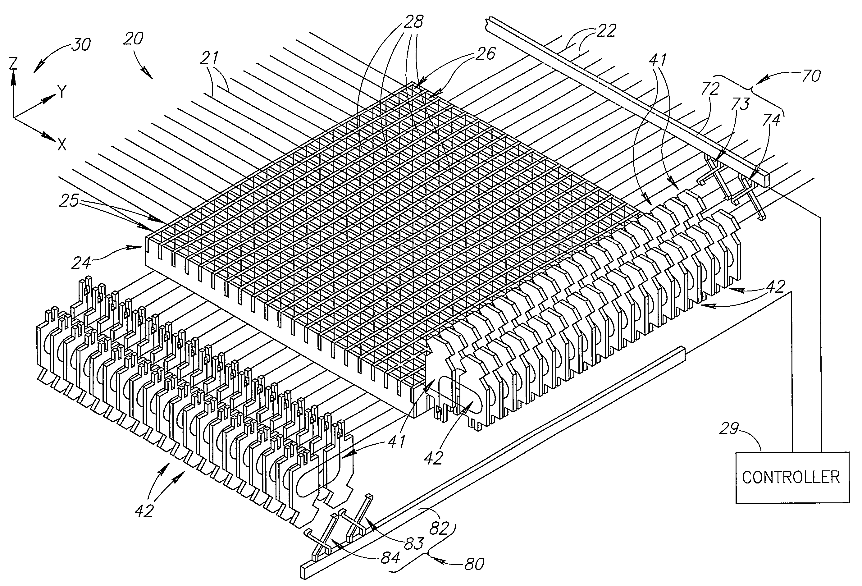
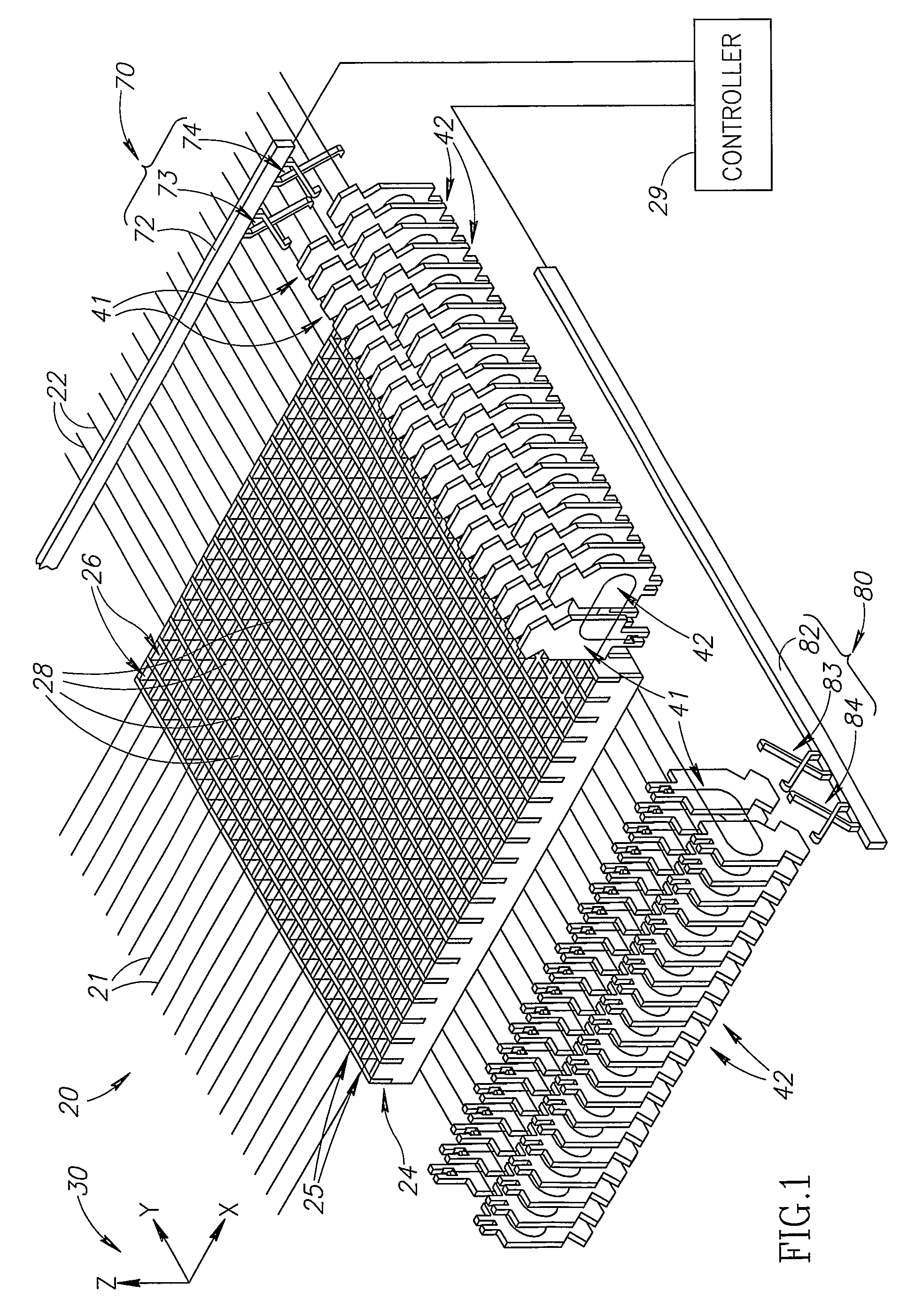
[0063]FIG. 1 schematically shows an optical crossbar switch 20, in accordance with an embodiment of the present invention. Crossbar switch 20 comprises a first plurality of optic fibers 21, hereinafter referred to as “top optic fibers”21, and a second plurality of optic fibers 22, hereinafter referred to as “bottom optic fibers”22. Optionally, within switch 20, top fibers 21 are coplanar and perpendicular to bottom fibers 22, which are optionally coplanar. Each optic fiber 21 and 22 is mounted to a fiber-end carriage 41 and a slack-control carriage 42, and is shown in FIG. 1 without obstruction by appurtenances that might be used to couple the fiber to the carriages in order to more clearly illustrate how the fiber is spatially configured, in accordance with an embodiment of the invention.

[0064]Optionally, crossbar switch 20 comprises a rectangular honeycomb array 24 of columns 25 and rows 26 of sockets 28 located between the plane of top fibers 21 and the plane of bot...


PUM

PropertyMeasurementUnit
radiusaaaaaaaaaa
radiusaaaaaaaaaa
radiiaaaaaaaaaa

Abstract

An optical crossbar switch for optically coupling optic fibers comprising: at least one first fiber (21) and a plurality of second fibers (22); a moveable fiber-end carriage (41) coupled to an end of the at least one first fiber and constrained to move along a predetermined trajectory; at least one moveable slack-control carriage (42) coupled to the body of the at least one first fiber and constrained to move along a predetermined trajectory; and at least one moving device (70, 80) controllable to move the carriages; wherein to optically couple a first fiber of the at least one first fiber to a second fiber of the plurality of second fibers, the at least one moving device moves the fiber-end carriage of the first fiber along its trajectory to a position at which the end of the first fiber is optically coupled to an end of the second fiber and moves the at least one slack-control carriage to take up slack in the first fiber generated by movement of its fiber-end carriage.

Description

RELATED APPLICATIONS[0001]The present application is a Continuation-In-Part of PCT / IL2004 / 001058 filed on Nov. 17, 2004 entitled “Optical Crossbar Switch”, the disclosure of which is incorporated herein by reference.FIELD OF THE INVENTION[0002]The invention relates to crossbar switches and in particular to optical crossbar switches.BACKGROUND OF THE INVENTION[0003]A crossbar switch generally operates to connect any one of a first plurality of signal ports to any one of a second plurality of signal ports. Generally, signal ports in the first and second pluralities of signal ports are bi-directional and any of the first or second ports in the crossbar switch can be used to both receive and transmit signals. The crossbar switch operates as a router that routes a signal received on any one of its ports in the first or second plurality of ports to a desired port of the other of the first and second plurality of ports from which the signal is transmitted. Crossbar switches are typically u...

Claims


Application Information

Patent Timeline
Patent Type & Authority Applications(United States)
IPC IPC(8): G02B6/26C08K3/36C09J133/04
CPCG02B6/3508G02B6/3574G02B6/3556G02B6/3548G02B6/35
Inventor AROL, JOSEPHAVRAHAMI, ZOHAREIZENSHTAT, MENACHEMCOHEN, RAHAVGANOR, ZE'EV
Owner WAVE2WAVE
Why Eureka
Try Eureka