Power connector with improved contacts

Inactive Publication Date: 2009-08-27
HON HAI PRECISION IND CO LTD
View PDF4 Cites 23 Cited by
  • Summary
  • Abstract
  • Description
  • Claims
  • Application Information

AI Technical Summary

Benefits of technology

[0006]A primary object, therefore, of the present invention is to provide a power con

Problems solved by technology

However, the second conductive contact 6 is substantially of columnar configura

Method used


Image

  • Power connector with improved contacts
  • Power connector with improved contacts
  • Power connector with improved contacts

Examples


Example

[0016]Reference will now be made in detail to a preferred embodiment of the present invention.

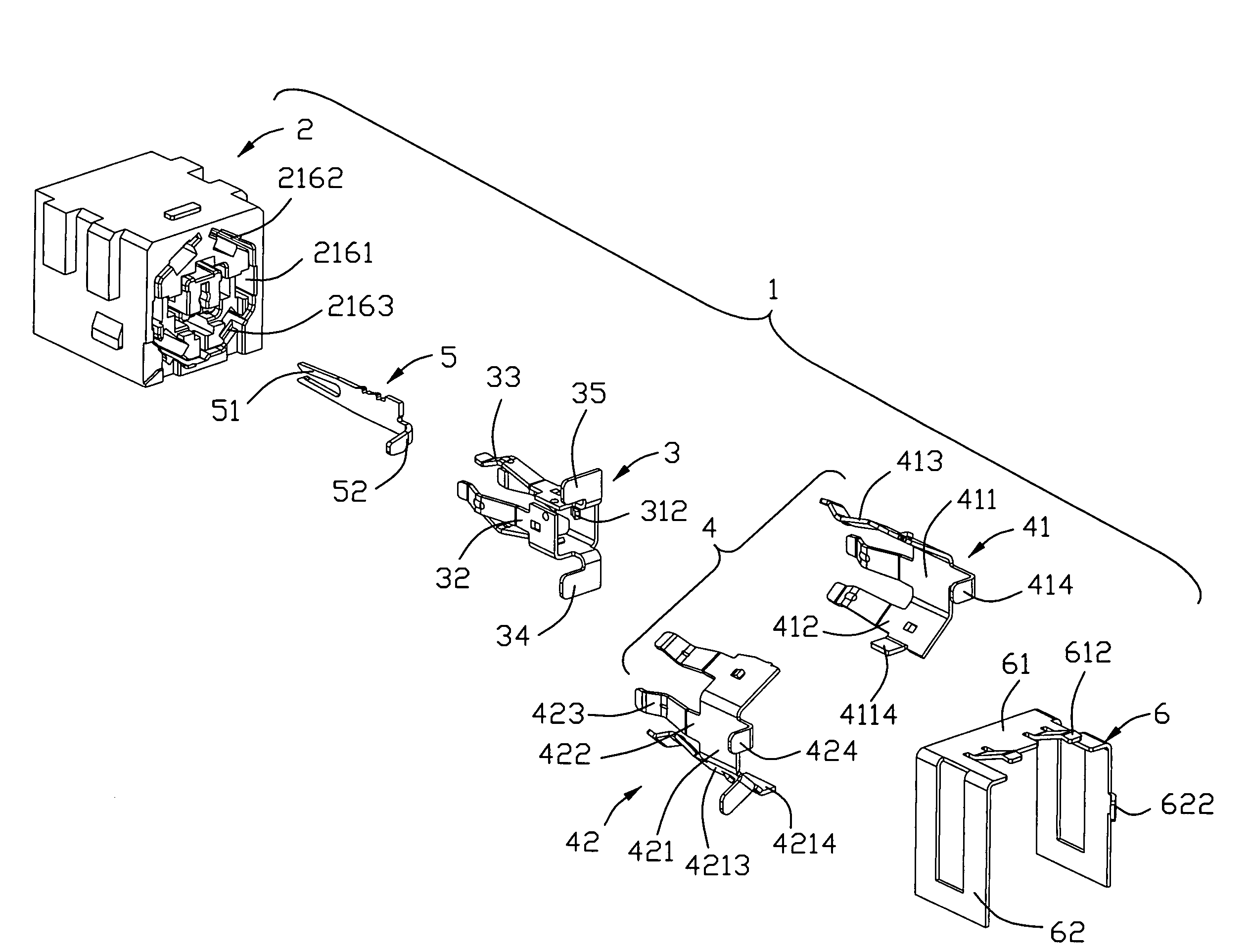
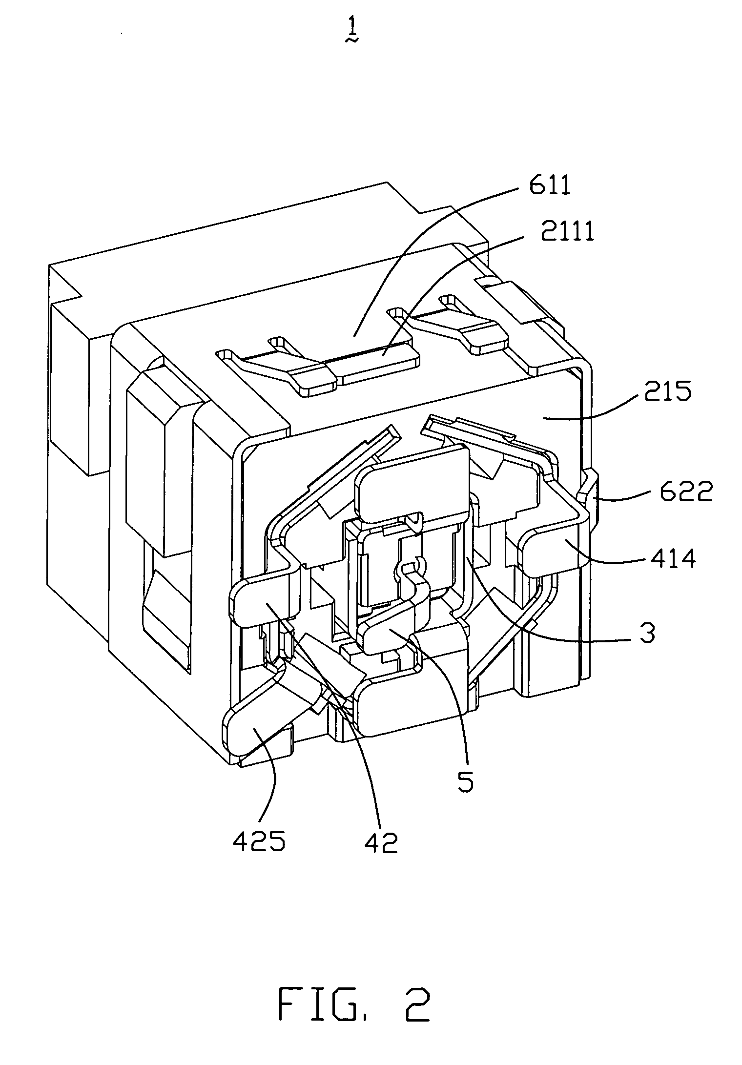
[0017]Referencing to FIGS. 1-5, a power connector of the present invention comprises an insulative housing 2, a first conductive contact 3 received in the insulative housing 2, a second conductive contact 4 having two separated portions, a conductive pin 5, and a conductive shield 6 covering the insulative housing 2.

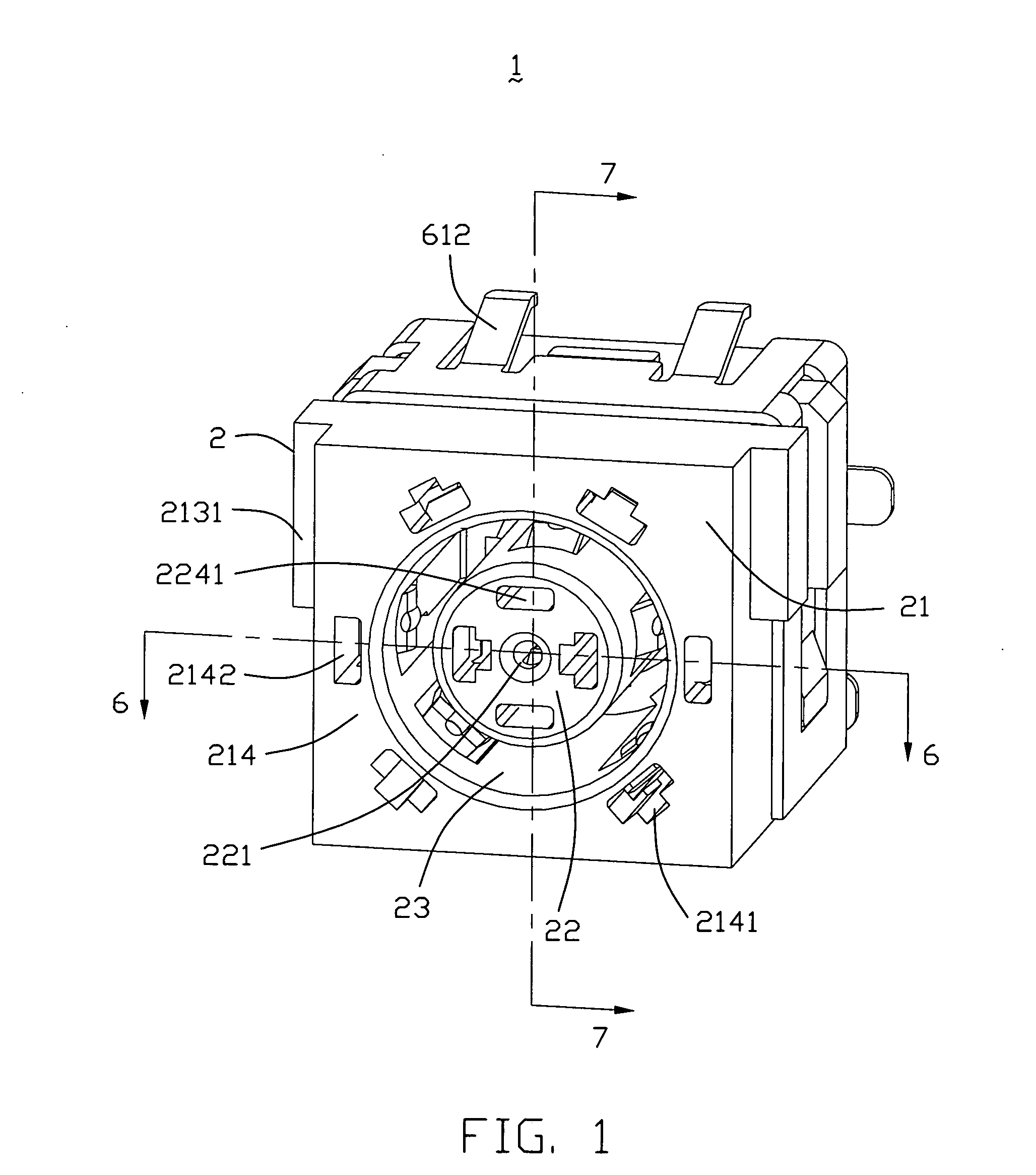
[0018]Referencing to FIGS. 1, 4, 6 and 7, the insulative housing 2 is of cubicial configuration. The insulative housing 2 comprises an outer portion 21 which comprises a top wall 211, a bottom wall 212, a pair of side walls 213 connecting the top wall 211 to the bottom wall 212, a front wall 214, and a rear wall 215. An annular receiving space 23 is defined therein and extends rearwards from a front face (not labeled) of the housing 2, creating a cylindrical inner portion 22 of the housing 2 which extends forwardly from a rear wall 215 of the housing 2 and is bounded on its side...


PUM


Abstract

An electrical connector includes an insulative housing, a plurality of terminals in the housing and a shield assembled on the housing. The terminals include a conductive grounding contact with separated first grounding contact and second grounding contact. The first grounding contact and second grounding contact respectively includes at least one soldering tail electrically connected to the shield for being electrically connected to each other.

Description

BACKGROUND OF THE INVENTION[0001]1. Field of the Invention[0002]The present invention relates generally to a Power connector, and more particularly to a Power connector having improved contacts connected cathode.[0003]2. Description of the Prior Art[0004]Direct current (DC) power connects are widely used in electronic devices to transmit electrical power to the devices. US. Pat. No. 6,695,644, issued to Zhao, Qi-jun, discloses a power connect with improved contact. Please refer to FIG. 2 of this patent, the power connector 1 comprises an insulative housing 2, a first conductive contact 5, a second conductive contact 6, a conductive pin 7 and a conductive shield 8. Each of the first conductive contact 5 and the second conductive contact 6 comprises a main body 51 assembly in the rear wall of the housing 2 and a plurality of mating portions 53 integrally formed with the main body 51 adapted for engaging with a contact of a mating connector, the mating portions 53 assembled in the hous...

Claims


Application Information

Patent Timeline
IPC IPC(8): H01R13/648
CPCH01R13/65802H01R13/6485H01R13/6582
Inventor CHENG, YUNG-CHANG
Owner HON HAI PRECISION IND CO LTD
Why Eureka
Try Eureka