Device for indicating the state of a switching apparatus

Active Publication Date: 2015-07-09
HITACHI ENERGY SWITZERLAND AG
View PDF1 Cites 2 Cited by
  • Summary
  • Abstract
  • Description
  • Claims
  • Application Information

AI Technical Summary

Benefits of technology

[0021]According to an embodiment of the invention, the second switch is arranged in parallel with the first mentioned switch and the power supply, and the electric circuit comprises a second resistor arranged in series with the second switch, formed by the second contact pin and the contact element, to achieve a differentiated voltage and current level compared to the first switch, and thus make it possible to detect the different positions.
[0022]According to an embodiment of the invention, the detector arrangement is configured to

Problems solved by technology

Many position detectors and indicators, however, suffer from disadvantages that render them insufficient in certain applications.
Many types of indicators are prone to breaking if used in applications that require higher speed and high acceleration.
However, commercially available micro switches can withstand only about 1 m/s.
To use detectors that are adapted for use at high speed such as an optical indicator, f

Method used


Image

  • Device for indicating the state of a switching apparatus
  • Device for indicating the state of a switching apparatus
  • Device for indicating the state of a switching apparatus

Examples


Example

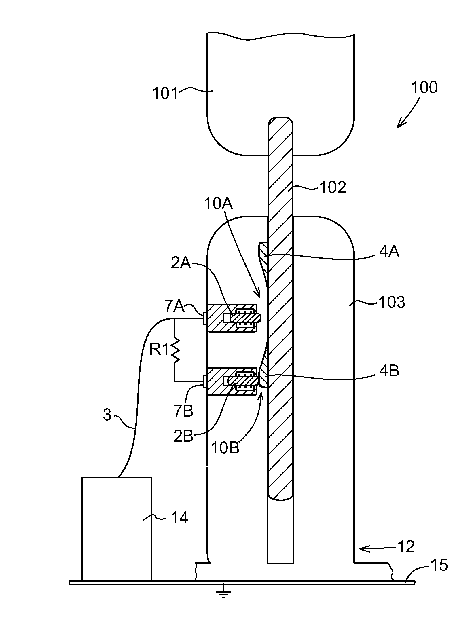
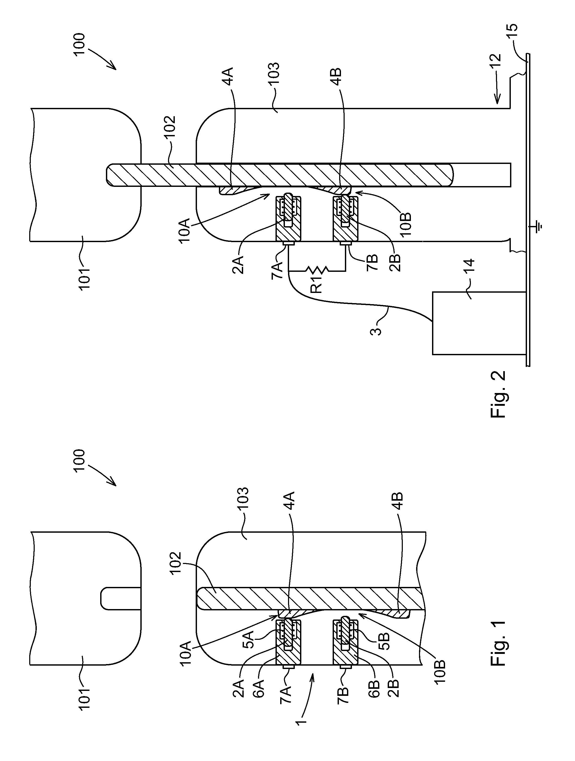
[0041]FIG. 4 shows a circuit diagram of an indication device according to a first embodiment of the invention. The indication device includes the position indicator 1 and a detection arrangement 8 for detecting the states of the switches 10A, 10B and by that the state of the switching apparatus 100, as will be described in more detail further below. The detection arrangement 8 comprises a power supply 8A and a resistor R2 connected to the power supply 8A and a measuring unit 8C, such as a voltmeter, that is arranged to measure a voltage between the resistor R2 and a known electrical potential, such as a local ground. In this case the control unit is configured to detect whether the movable contact 102 is in the first or second position based on the level of the measured voltage. Two detector terminals 8D, 8E are provided for output and input to the detection arrangement 8. The detector arrangement 8 can be a part of the control unit 14 of the switching apparatus.

[0042]Alternatively,...

Example

[0053]In this second embodiment, if a power source 8A of 10 V is used, as in the example given above, the measuring unit 8C would detect 0 V if the switching apparatus 100 is in the first, i.e. open, state and 10 V if it is not. In this embodiment, both a closed state and a malfunction would give the same value to the measuring unit 8C.

[0054]The circuit diagram for this second preferred embodiment differs from that shown in FIG. 4 in that the second switch 10B and the resistor R1 are eliminated, leaving only the resistor R2 and the first switch 10A, together with the input / output connections (via the insulated connector to point 8D and the connection through the support structure to point 8E, respectively) in the indication device 1.

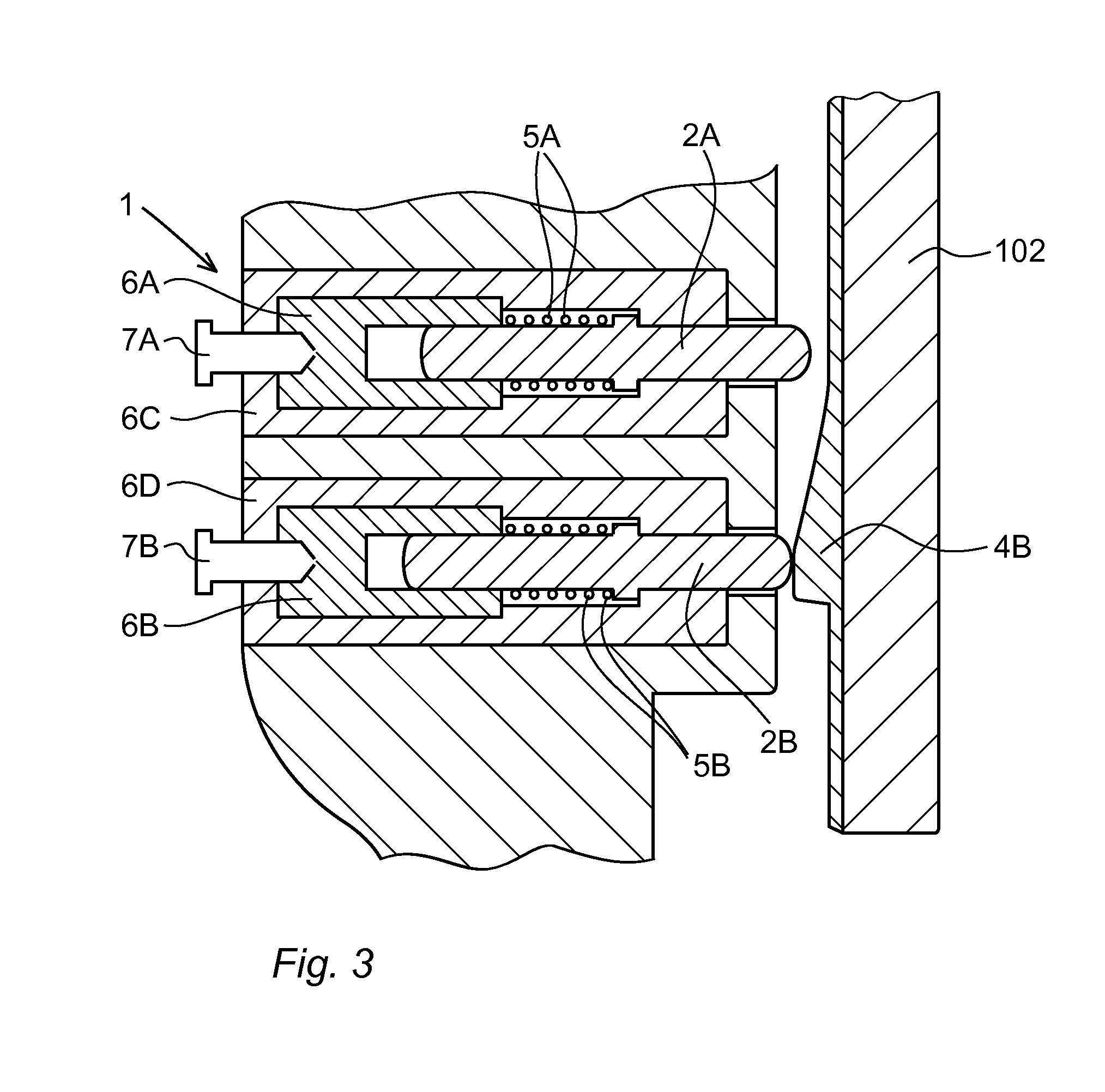
[0055]Thanks to the invention according to any of the embodiments, the state of a fast closing switching apparatus can be detected in a safe way. By the interaction of the movable contact with the contact elements, the contact pins and the springs, the s...


PUM


Abstract

A device for indicating the state of an electrical switching apparatus includes a movable contact arranged movable between a first and a second position. The device includes at least one protruding contact element arranged on the movable contact, at least one contact pin arranged in the close vicinity to the movable contact such that said contact element abuts the contact pin when the movable contact is in the first position and said contact element is at a distance from the contact pin when the movable contact is in the second position. The contact element and the contact pin form an electrical switch and a detector arrangement configured to detect when said electrical switch is closed and by that detect when the movable contact is in the first position.

Description

FIELD OF THE INVENTION[0001]The present invention relates to a device for indicating the state of an electrical switching apparatus including a movable contact, movable between a first and a second position.PRIOR ART[0002]A switching apparatus might be a closer for quick closing an electric circuit, in particular of a medium or high voltage level. Such a switching apparatus normally has two contacts movable relative each other. Usually the movement is linear. The relative movement can either be achieved in that one of the contacts is movable and the other stationary, or in that both contacts are movable.[0003]The use of a switching apparatus including a movable contact in technical applications for opening and closing an electrical circuit is common and widespread in many fields. Associated therewith is also the need to determine whether a particular switching apparatus is in an open or closed state, for instance to determine if a device is safe to touch during service or that an op...

Claims


Application Information

Patent Timeline
IPC IPC(8): H01H9/16
CPCH01H9/16H01H1/0015H01H9/0066H01H71/04H01H71/46H01H73/12H01H9/00
Inventor JOHANSSON, DANIEL
Owner HITACHI ENERGY SWITZERLAND AG
Why Eureka
Try Eureka