Flat plunger round barrel test probe

Inactive Publication Date: 2010-08-05
XCERRA
View PDF20 Cites 2 Cited by
  • Summary
  • Abstract
  • Description
  • Claims
  • Application Information

AI Technical Summary

Benefits of technology

[0011]The present invention is directed to a spring contact assembly having a flat plunger, a cylindrical barrel and a compression spring wherein the plunger has a biasing feature to improve contact with the barrel. The contact tip can have a number of configurations

Problems solved by technology

A problem associated with these type of external spring probes is the expense to manufacture due to costly machining operations.
A

Method used


Image

  • Flat plunger round barrel test probe
  • Flat plunger round barrel test probe
  • Flat plunger round barrel test probe

Examples


Example

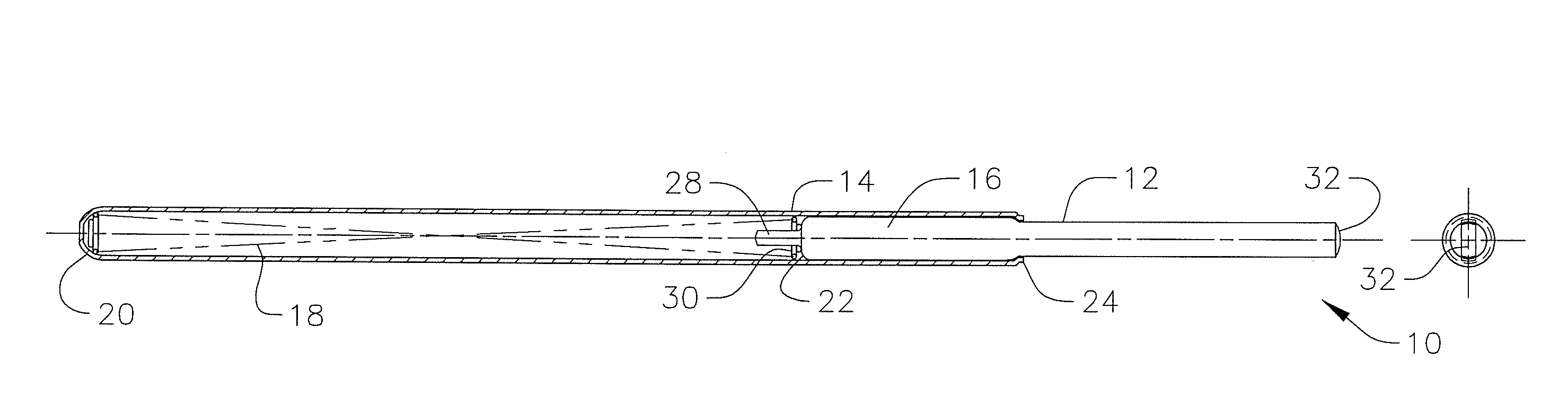
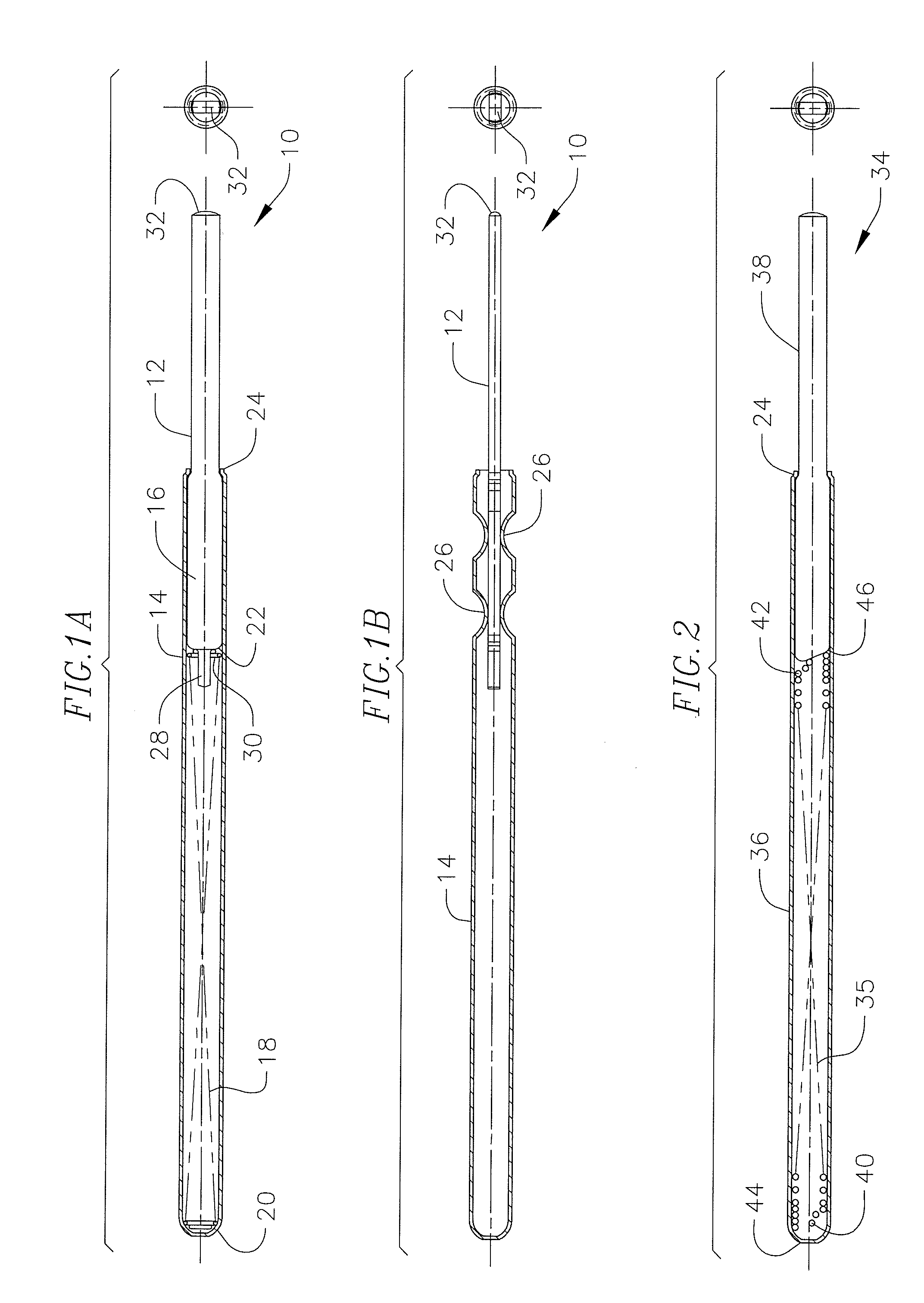
[0030]FIGS. 1A and 1B illustrate an exemplary spring contact assembly 10 of the present invention. The spring contact assembly 10 includes a plunger 12 partially positioned within a barrel 14. The plunger 12 has a flat configuration and has a wider portion 16 which is retained within the tubular barrel 14. A round compression spring 18 is positioned within the tubular barrel between a closed end 20 of the barrel and end 22 of wider portion 16 of the plunger. The wider portion 16 of the plunger slidably engages the inner surface of the barrel. The wider bearing portion is retained in the barrel by a crimp or close 24 on an end of the barrel opposite end 20. Crimp 24 defines an opening for the plunger to extend out of and be compressed into the barrel. The plunger 12 is normally biased outwardly a selected distance by the spring and may be depressed inwardly into the barrel under force directed against the spring.

[0031]As shown in FIG. 1B, the barrel can have a plurality of guiding cr...


PUM


Abstract

A spring probe utilizing a flat plunger and a round barrel having a compression spring positioned within the barrel and a wiper for internal contact between the plunger and the inside of the barrel.

Description

CROSS-REFERENCE TO RELATED APPLICATION(S)[0001]This application claims priority to U.S. Provisional Application No. 61 / 148,657 filed Jan. 30, 2009.FIELD OF THE INVENTION[0002]The present invention relates to electrical contact probes forming electrical interconnects and, more particularly, to contact probes having a flat plunger and a round barrel.BACKGROUND OF THE INVENTION[0003]Conventional spring loaded contact probes generally include a movable round plunger and a tubular barrel having an open end for containing an enlarged diameter section of the plunger, and a spring for biasing the travel of the plunger in the barrel. The plunger bearing slidably engages the inner surface of the barrel. The enlarged bearing section is retained in the barrel by a crimp near the barrel open end. The plunger is commonly biased outwardly, a selected distance by the spring and may be biased or depressed inwardly into the barrel, a selected distance, under force directed against the spring. Axial a...

Claims


Application Information

Patent Timeline
IPC IPC(8): H01R4/48
CPCG01R1/06738G01R1/06722G01R1/067G01R31/307
Inventor SWART, MARK A.SARGEANT, STEVE B.JOHNSTON, CHARLES J.
Owner XCERRA
Why Eureka
Try Eureka