Helical conveyor centrifuge

a conveyor and helical technology, applied in the direction of centrifuges, rotary centrifuges, etc., can solve the problems of only partially solved problems, clogging of tubes, and affecting the operation of conveyors, so as to achieve the effect of keeping deposits fr

Inactive Publication Date: 2009-08-27
HILLER
View PDF38 Cites 0 Cited by
  • Summary
  • Abstract
  • Description
  • Claims
  • Application Information

AI Technical Summary

Benefits of technology

[0010]The result of the invention is on the one hand that product deposits cannot settle in the comparatively large cavity of the hollow shaft, while simultaneously eliminating the danger that the comparatively narrow protective tube can be clogge

Problems solved by technology

However, product deposits may over time become baked into such cavity and in particular into dead spaces thereof, and thus produce an imbalance on the rotating conveyor screw.
The problem is only partially solved in

Method used


Image

  • Helical conveyor centrifuge
  • Helical conveyor centrifuge
  • Helical conveyor centrifuge

Examples


Embodiment Construction

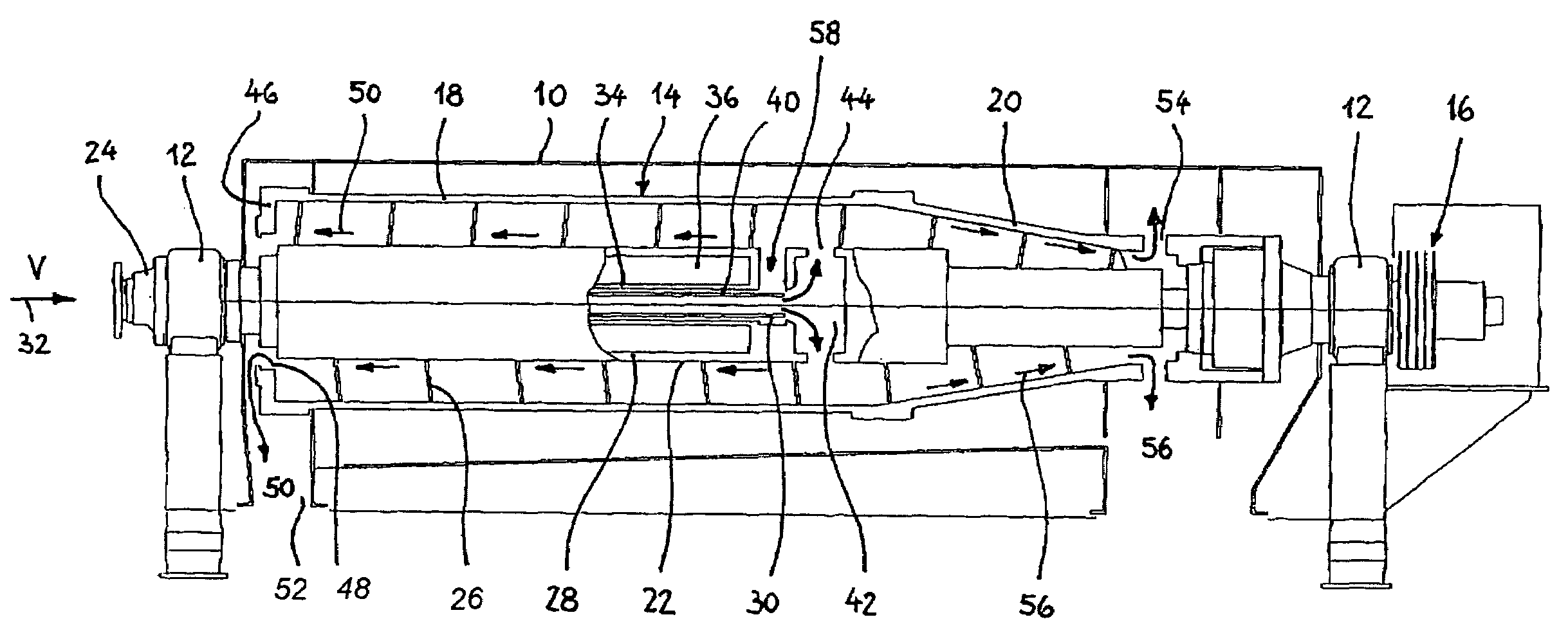
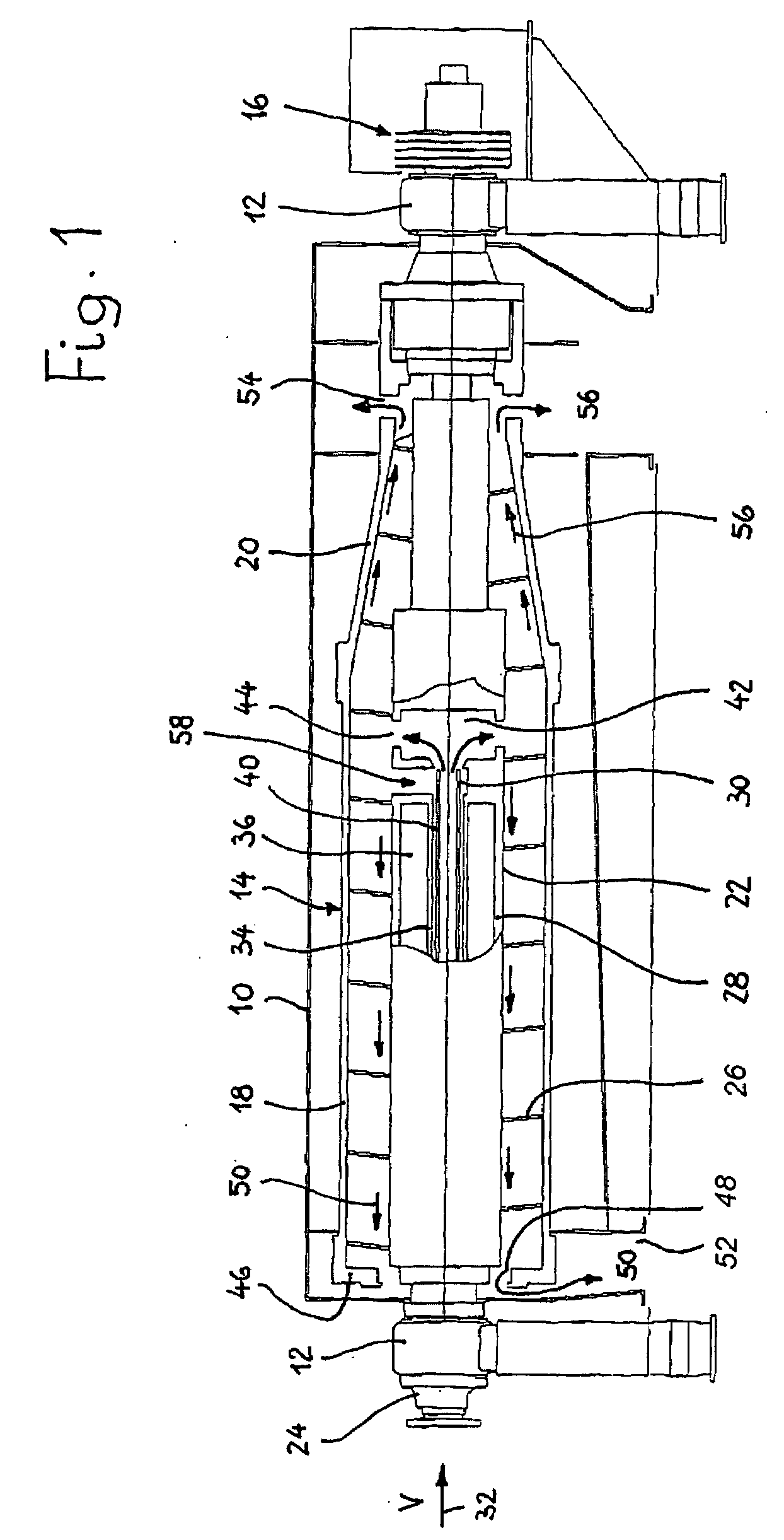
[0015]FIG. 1 illustrates a rotor drum 14 that is driven by a motor 16 rotatably journaled in bearings 12 in a housing 10 (only partially indicated). Rotor drum 14 is made up of a cylindrical portion 18 and a conical portion 20. Journaled rotatably in rotor drum 14 is a conveyor screw 22 that is driven by a motor 24 at a generally slightly higher rotation speed than rotor drum 14. Screw blade 26 of conveyor screw 24 is mounted on a hollow shaft 28, and is arranged so that the conveying direction is from cylindrical portion 18 toward conical portion 20.

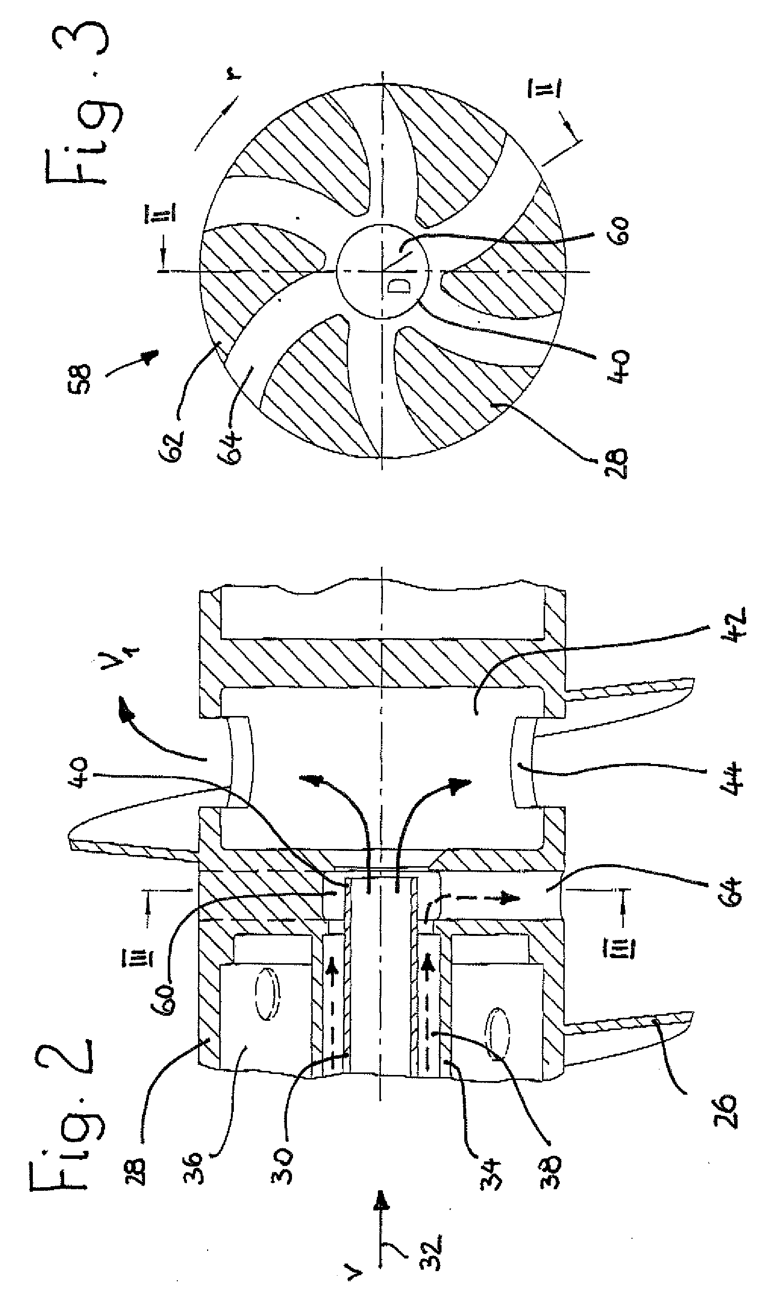
[0016]Arranged inside hollow shaft 28 is an inflow tube 30 for the mixture to be separated, which enters inflow tube 30 in the direction of arrow 32. Inflow tube 30 extends through a coaxial protective tube 34 that is fixedly joined to hollow shaft 28 and delimits cavity 36 of hollow shaft 28 from annular space 38 (FIG. 2) that encloses inflow tube 30.

[0017]Free end 40 of inflow tube 30 leads into a feed chamber 42, configured in hollow...


PUM


Abstract

A screw centrifuge for the continuous separation of flowable substances of different densities includes a rotor drum having discharge openings for the heavy phase that are arranged in a conical portion of the rotor wall, and weir openings for the light phase that are provided on an end wall of the rotor drum. A conveyor screw is rotatable inside the rotor drum and has a screw blade mounted on a hollow shaft for transporting the heavy phase to the discharge openings. A mixture inflow tube is arranged coaxially inside the hollow shaft and leads to a feed chamber in the hollow shaft that is in flow communication with the screw blade. An air extraction member is provided before the feed chamber and generates, in the annular space enclosing the inflow tube, a suction flow co-directional with the delivery direction in the inflow tube.

Description

FIELD OF THE INVENTION[0001]The present invention relates to a screw centrifuge for the continuous separation of flowable substances of different densities. More particularly, the present invention relates to a screw centrifuge, in which an air extraction member is provided before a feed chamber to generate a suction flow co-directional with the delivery direction of an inflow tube.BACKGROUND OF THE INVENTION[0002]In screw centrifuges for the continuous separation of flowable substances of different kinds, one critical area is where the mixture inflow tube leads into the feed chamber, since portions of the mixture may flow back, because of turbulence or excessive throughput, into the cavity of a hollow shaft of a conveying screw and become deposited inside a cavity of the conveying screw. To remedy this problem, in known designs openings are provided in the wall of the hollow shaft of the conveying screw, through which openings these product deposits can escape into the region of th...

Claims


Application Information

Patent Timeline
IPC IPC(8): B04B15/08
CPCB04B1/20B04B2001/2033B04B11/06
Inventor HAIDER, GUENTERKLINGER, KLAUS
Owner HILLER
Why Eureka
Try Eureka