Apparatus for detecting malfunctions of electromagnetic brakes of robot

a technology of electromagnetic brakes and actuators, which is applied in the direction of dynamo-electric converter control, program control, instruments, etc., can solve the problems of insufficient countermeasures, slow arm drop, and inability to detect malfunctions of electromagnetic brakes, so as to suppress inadvertent motion of robots and reliably detect malfunctions

Active Publication Date: 2009-08-27
DENSO WAVE INC
View PDF2 Cites 13 Cited by
  • Summary
  • Abstract
  • Description
  • Claims
  • Application Information

AI Technical Summary

Benefits of technology

[0010]The present invention has been made in consideration of the above-stated situations, and it is an object of the present invention to provide an apparatus for detecting malfunctions of electromagnetic brakes for a robot in a reliable manner, while still suppressing inadvertent motions of the robot during the detection. The present invention also provides a method of reliably detecting such malfunctions.

Problems solved by technology

This break mechanism may operate erroneously when the relay(s) causes a malfunction, even if the electromagnetic brake itself can work normally.
However, this countermeasure is not sufficient, because the regenerating brake by itself cannot prevent the arm form dropping down, although it can make the dropping speed of the arm slower.
However, when this kind of malfunction detecting technique is applied to an industrial robot, there remains a drawback which cannot be removed by this technique.
Hence, if the brake mechanism for motors driving arms causes a malfunction, the locking action is performed after detecting the malfunction, which results in an after-the-fact control.
It is thus impossible to avoid the arms from drooping in a reliable manner.

Method used


Image

  • Apparatus for detecting malfunctions of electromagnetic brakes of robot
  • Apparatus for detecting malfunctions of electromagnetic brakes of robot
  • Apparatus for detecting malfunctions of electromagnetic brakes of robot

Examples


first embodiment

[0029]Referring to FIGS. 1-5, a first embodiment of the robot controller according to the present invention will now be described.

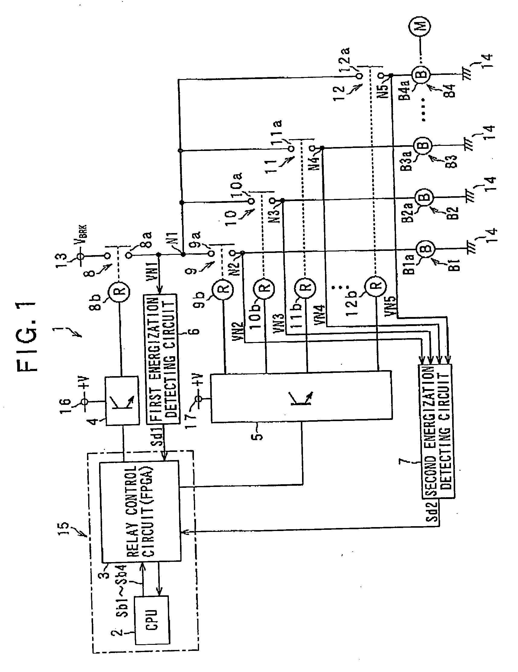
[0030]An industrial robot (not shown), to which a robot controller according to the present embodiment is provided, has a plurality of electric motors to actuate arms serving as movable portions of the robot and a plurality of electromagnetic brakes to brake the rotation of the motors. FIG. 1 shows part of the robot controller that controls such a robot, which part of the robot controller shows components to control the electromagnetic brakes.

[0031]In FIG. 1, the plurality of electromagnetic brakes are shown by four references B1-B4, which engage in controlling the operations of the motors (not shown). The electromagnetic brakes B1-B4 are provided with exaction coils B1a-B4a, respectively, and are produced as unexcitable operating type of electromagnetic brakes which operate to lock the brakes when the excitation cols B1a-B4a are non-excited.

[0032]By the ...

second embodiment

[0066]Referring to FIGS. 610, a second embodiment of the robot controller according to the present invention will now be described.

[0067]In the second embodiment, the similar or identical components to those in the first embodiment will be given the same reference numerals for the sake of a simplified description.

[0068]FIG. 6 shows a robot controller 21 according to the second embodiment, where this controller 21 is different from the robot controller 1 of the first embodiment in that there are provided a CPU 22, a relay control circuit 23, and encoders E1-E4 instead of the CPU 2, the relay control circuit 3 and the second energization detecting circuit 7.

[0069]The encoders E1-E4, which compose motor rotation detecting means, are produced to output pulse signals Sp1-Sp4 depending on rotating positions of plural motors M1-M4 assembled with the robot, respectively. These encoders, which are integrally assembled with the motors, respectively, are thus used to control the rotation of th...


PUM


Abstract

An apparatus is provided for detecting a malfunction occurring in an electromagnetic brake of a robot. In the apparatus, the main relay and the sub-relay are controlled to open the main contact and the sub-contact when the robot is activated. Detecting is then made whether or not the main contact is malfunctioning, by monitoring an energized state of the main contact. Activation of the robot is stopped when the main contact is malfunctioning and the main relay is controlled to close the main contact for a given period of time when that the main contact is operating normally. Detecting is further made as to whether or not the sub-contact is malfunctioning, by monitoring an energized state of the sub-contact The activation of the robot is stopped when the sub-contact is malfunctioning and the main relay is controlled to close the main contact when the sub-contact is operating normally.

Description

CROSS-REFERENCE TO RELATED APPLICATION[0001]This application is based on and claims the benefit of priority from earlier Japanese Patent Application No. 2008-040020 filed Feb. 21, 2008, the description of which is incorporated herein by reference.BACKGROUND OF THE INVENTION[0002]1. Technical Field of the Invention[0003]The present invention relates to an apparatus for detecting malfunctions of electromagnetic brakes for braking motors incorporated in a robot and how to check malfunctions of the electromagnetic brakes.[0004]2. Related Art[0005]In robots such as industrial robots working in factories, brake mechanisms that brake electric motors to drive robot arms are essential in properly controlling the coordinates positions and attitudes of robot joints of the arms. In general, each of the brake mechanisms is provided with an electromagnetic brake braking a motor with an excitation coil and relays switching over between the current supply state (energized) and the current no-supply...

Claims


Application Information

Patent Timeline
Patent Type & Authority Applications(United States)
IPC IPC(8): G06F19/00B25J19/06F16D65/14F16D65/28
CPCB25J9/1674G05B2219/41279B25J19/0004
Inventor WATANABE, KAZUNORIINAGAKI, TAKAMITSU
Owner DENSO WAVE INC
Why Eureka
Try Eureka