

Joint guard for panels
a joint guard and panel technology, applied in the field of joint guards, can solve the problems of radically reducing affecting the operation of the floor, and affecting the useful life of the floor,
Inactive Publication Date: 2009-09-03
PERGO
View PDF25 Cites 119 Cited by
- Summary
- Abstract
- Description
- Claims
- Application Information
AI Technical Summary
Benefits of technology
[0007]According to one embodiment of the invention the joint guard is provided with a locking tongue stopper. The locking tongue stopper is intended to ensure that the moveable locking element is kept in a default position during the milling as well as keeping it from getting caught in the teeth of the saw during the cutting operation.
[0008]According to one embodiment of the invention the joint guard is provided with a locking tongue leg support and a maneuvering leg support. The locking tongue leg support and maneuvering leg support is intended to ensure that the moveable locking element and maneuvering leg is kept in a default position during the milling as well as keeping it from getting caught in the teeth of the saw during the cutting operation.
[0012]According to one embodiment of the invention the joint guard is provided with a maneuvering cheek support. The maneuvering cheek support is intended to ensure that the moveable locking element is kept in a default position during the milling as well as keeping it from getting caught in the teeth of the saw during the cutting operation.
[0013]According to one embodiment of the invention the joint guard is provided with a outer locking tongue support. The outer locking tongue support is intended to ensure that the moveable locking element is kept in a default position during the milling as well as keeping it from getting caught in the teeth of the saw and deformed during the cutting operation.
[0016]The joint guard according to the present invention is primarily used during cutting of panels and is then applied to the edge very much like another panel would be. The biggest difference between another panel and the joint guard is that the joint guard is designed not to engage or activate the different locking mechanisms of the panel edge. As will he evident when studying enclosed embodiment examples of joints in the present invention, some embodiment of joint will not be easily disassembled once two panels are joined together. The joint guard is therefore designed to hold the locking mechanism in place without activating it. The joint guard is furthermore so designed as to not cause any substantial wear or deformation on functional parts such as locking edges and the like on embodiments herein described as well as on embodiment disclosed by reference. The joint guard is then applied on the edge of the panel to be cut and the cutting may commence. The cutting is either performed through the joint guard or using the joint guard as a ruler. It is however advantageous to arrange the joint guard on the portion of the panel that is to be used in the installation. The joint guard is advantageously also used as a tapping block during the installation of floor panels.
[0023]According to one special embodiment the locking element is provided with a hinge. This will allow a snap-action cam lock effect.
Problems solved by technology
The most common types of tongue and groove are however burdened with the disadvantage to form gaps of varying width between the floor boards in cases where the installer hasn't been thorough enough.
The expansion will, cause the surface layer to rise closest to the edges of the joint which radically reduces the useful life of the floor since the surface layer will be exposed to an exceptional wear.
This operation is however more or less awkward.
This is a delicate part which is easily damaged when cutting the panel in connection to the assembly.
The locking parts of these type of floor panels are delicate and easily damaged but once properly installed, are still very strong.
Method used
View moreImage
Smart ImageViewing Examples

Examples
first embodiment
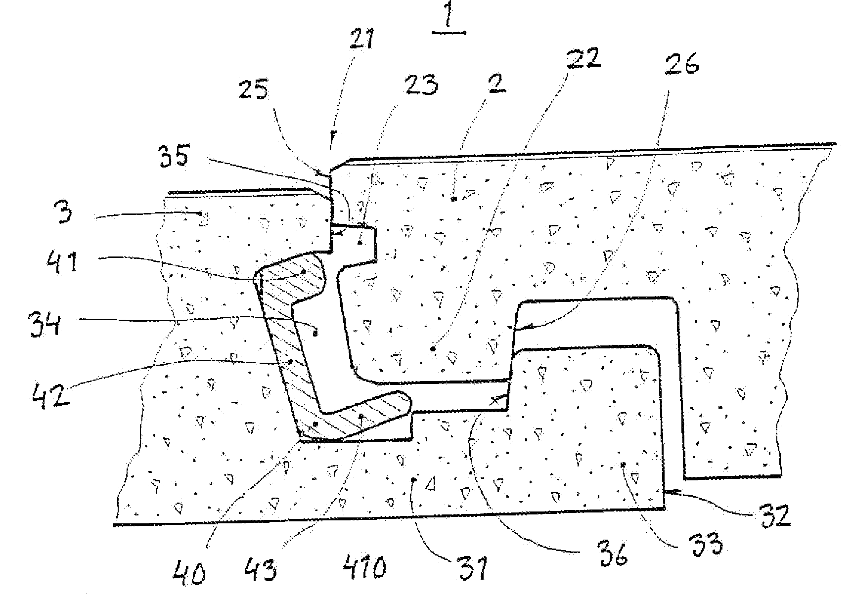
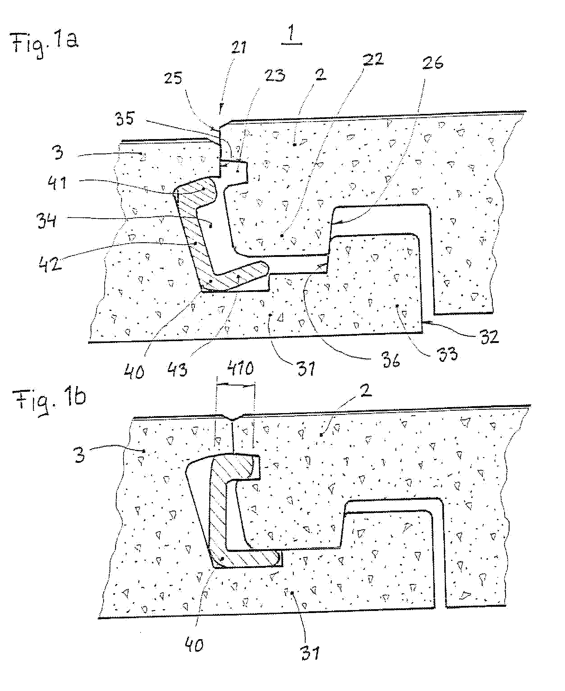
[0036]FIG. 1a-b shows a joint 1.
second embodiment
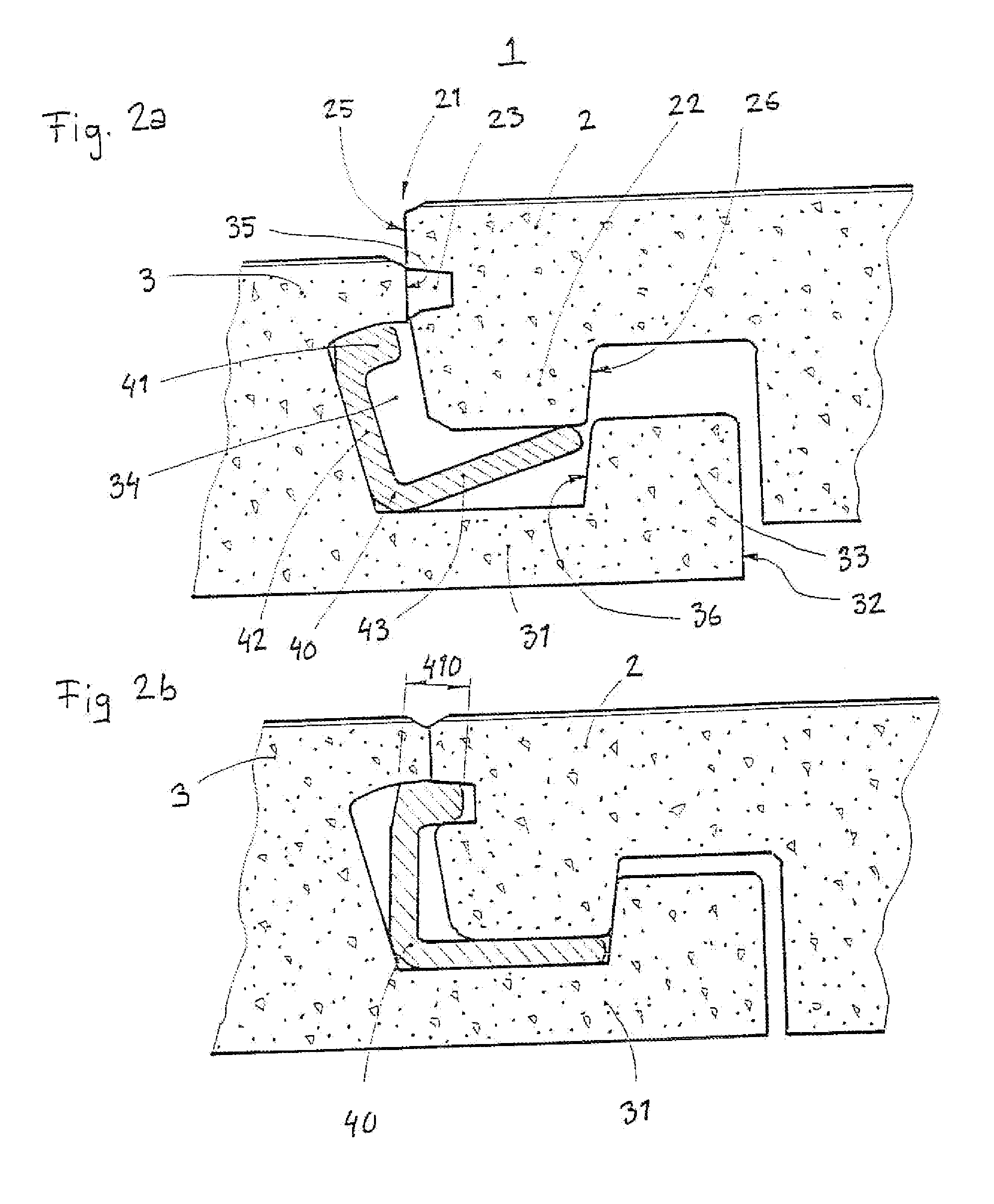
[0037]FIG. 2a -b shows a joint 1.
third embodiment
[0038]FIG. 3a -b shows a joint 1.
Login to View More PUM
 Abstract
A joint guard (100) provided with means for protecting, and stabilizing portions in the edge region of a panel, said portions being selected from the group consisting of; a distal edge (21), a downwards protruding heel (22), a upper joint edge (25), a groove (23), a lower cheek (31), a distal end (32), an upwards protruding lower cheek heel (33), an upper joining edge (35), an undercut (34), a moveable locking element (40), a locking tongue (41), a locking tongue leg (42) and a maneuvering leg (43).
Description
BACKGROUND OF THE INVENTION[0001]1. Field of the Invention[0002]The present invention relates to a joint guard used when cutting panels.[0003]2. Description of Related Prior Art[0004]Prefabricated floor boards provided with tongue and groove at the edges are quite common nowadays. These can be installed by the average handy man as they are very easy to install. Such floors can, for example, be constituted of solid wood, fiber board or particle board. These are most often provided with a surface layer such as lacquer, or some kind of laminate. The boards are most often installed by being glued via tongue and groove. The most common types of tongue and groove are however burdened with the disadvantage to form gaps of varying width between the floor boards in cases where the installer hasn't been thorough enough. Dirt will easily collect in such gaps. Moisture will furthermore enter the gaps which will cause the core to expand in cases where it is made of wood, fiber board or particle ...
Claims
Login to View More Application Information
Patent Timeline
 Patent Type & AuthorityApplications(United States)
IPC IPC(8): E04B5/00
CPCE04F15/02E04F15/04E04F21/22E04F2201/0115E04F15/02038E04F2201/0153E04F2201/0523E04B1/54E04F15/02022E04F2201/0138E04F2201/0552E04F2201/0535E04F2201/0547E04F2201/05E04B1/541
InventorENGSTROM, NILS-ERIK
OwnerPERGO