Methods for measuring the tension of optical fibers during manufacture

a technology of tension measurement and manufacturing method, which is applied in the direction of lighting and heating apparatus, instruments, furniture, etc., can solve the problems of costly process downtime, adverse effects on optical fiber properties, damage to optical fibers,

Inactive Publication Date: 2009-09-03
CORNING INC
View PDF2 Cites 28 Cited by
  • Summary
  • Abstract
  • Description
  • Claims
  • Application Information

AI Technical Summary

Benefits of technology

[0007]In one embodiment, a non-contact method for measuring the tension applied to a drawn optical fiber includes drawing an optical fiber and applying a pressurized fluid to the optical fiber to displace and / or reroute the optical fiber. The pressurized fluid may be applied to the optical fiber using, for example, a fluid bearing, one or more jets of pressurized fluid, and / or combinations thereof. The displacement of the optical fiber caused by the application of the pressurized fluid to the optical fiber may then be measured. The tension applied to the optical fiber may then be determined based on the determined displacement and the pressure and / or flow rate of the pressurized fluid.

Problems solved by technology

Excess draw tension applied to the optical fiber may damage the optical fiber or otherwise adversely effect the properties of the optical fiber.
Moreover, excess draw tension may cause the optical fiber to break thereby resulting in costly process downtime while the optical fiber is rerouted through the system and the process is restarted.
However, mechanical vibrations in the optical fiber are susceptible to background acoustic noise generated or present during the drawing process.
The acoustic noise may introduce error in the draw tension measurement.

Method used


Image

  • Methods for measuring the tension of optical fibers during manufacture
  • Methods for measuring the tension of optical fibers during manufacture
  • Methods for measuring the tension of optical fibers during manufacture

Examples


Embodiment Construction

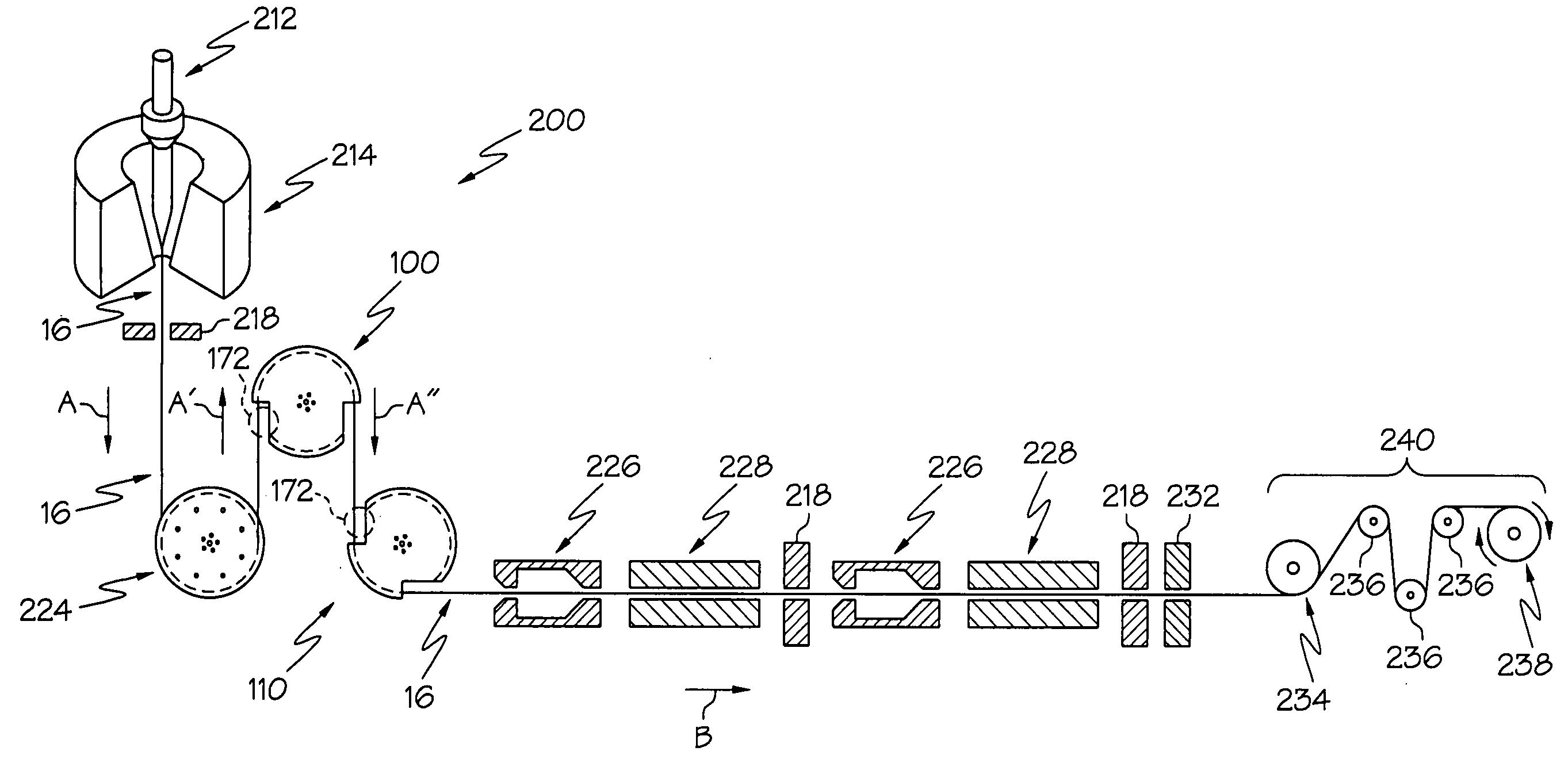
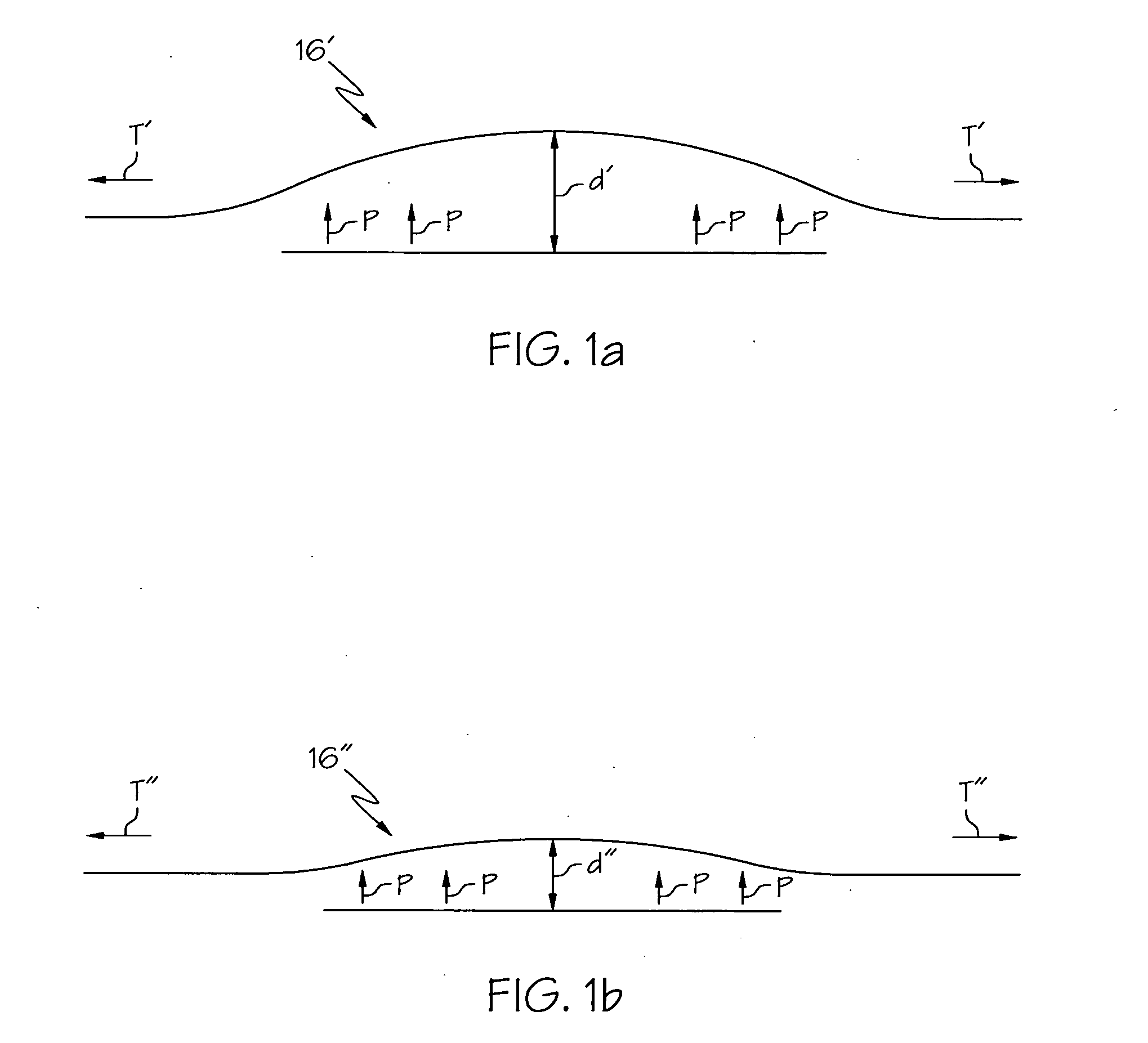
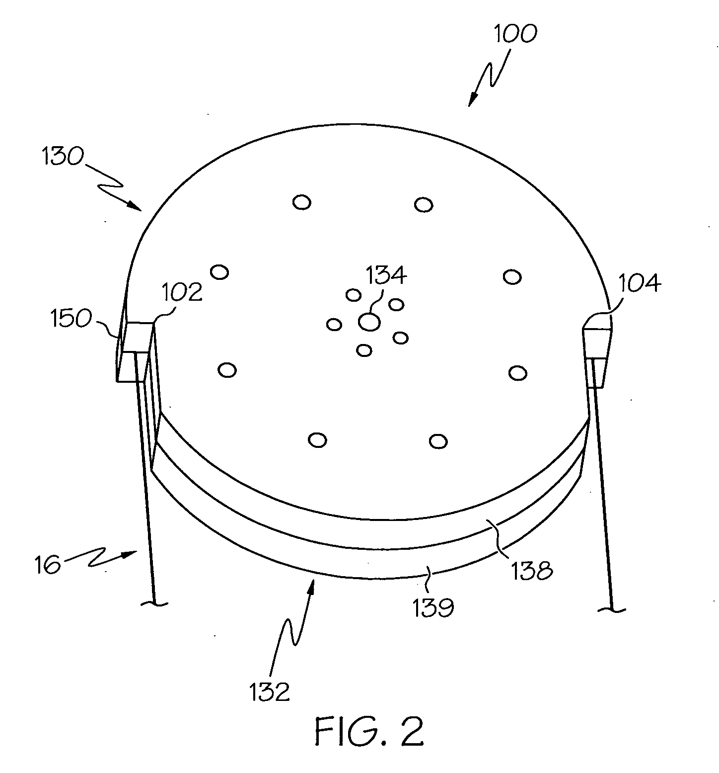
[0019]The methods described herein relate to the manufacture of optical fibers and, more specifically, to non-contact methods for measuring the tension applied to an optical fiber during a fiber drawing process. The method, schematically shown in FIGS. 1A and 1B, may comprise applying a pressurized fluid to the optical fiber to displace the optical fiber. The position of the optical fiber resulting from the application of the applied pressurized fluid is then used to determine the tension applied to the optical fiber based on a predetermined relationship between displacement and applied draw tensions for a particular pressure and / or a particular flow rate of applied pressurized fluid. FIGS. 2 and 3 illustrate one embodiment of a fluid bearing which may be used in conjunction with the methods described herein to measure the tension of an optical fiber during the fiber drawing process. The fluid bearing may generally comprise a fiber support channel. The fluid bearing may also contain...


PUM

PropertyMeasurementUnit
outer diameteraaaaaaaaaa

Abstract

A non-contact method for measuring the tension applied to a drawn optical fiber includes drawing an optical fiber and displacing the optical fiber by applying a pressurized fluid to the optical fiber. The pressurized fluid may be applied to the optical fiber using a fluid bearing. The fluid bearing may include a fiber support channel. The optical fiber may be directed through the fiber support channel and is displaced relative to the fluid bearing by supplying the pressurized fluid to the fiber support channel. The displacement of the optical fiber caused by the application of the pressurized fluid to the optical fiber may then be measured. The tension applied to the optical fiber may then be determined based on the determined displacement.

Description

CROSS-REFERENCE TO RELATED APPLICATIONS[0001]This application claims the benefit of, and priority to U.S. Provisional Patent Application No. 61 / 067,486 filed on Feb. 28, 2008, the content of which is relied upon and incorporated herein by reference in its entirety.BACKGROUND OF THE INVENTION[0002]1. Field of the Invention[0003]The present invention relates to methods for manufacturing optical fibers and, more specifically, to methods for measuring the tension applied to optical fibers during manufacture.[0004]2. Background of the Invention[0005]The measurement of the draw tension applied to an optical fiber during an optical fiber drawing process is critical to the fiber drawing process. Excess draw tension applied to the optical fiber may damage the optical fiber or otherwise adversely effect the properties of the optical fiber. Moreover, excess draw tension may cause the optical fiber to break thereby resulting in costly process downtime while the optical fiber is rerouted through...

Claims


Application Information

Patent Timeline
Patent Type & Authority Applications(United States)
IPC IPC(8): C03B37/07G01N21/00
CPCC03B2205/40C03B37/0253
Inventor COSTELLO, III, JOHN JOSEPHFILIPPOV, ANDREY V.
Owner CORNING INC
Why Eureka
Try Eureka