Systems and Methods for Calibrating Triaxial Accelerometers

a triaxial accelerometer and calibration system technology, applied in the field of accelerometers, can solve the problems of inexact orientation, inaccuracy, and inability to produce the most accurate outputs averaging these individually-calibrated outputs, and achieve the effect of optimizing the calibration constan

Active Publication Date: 2009-09-03
BAKER HUGHES INC
View PDF4 Cites 40 Cited by
  • Summary
  • Abstract
  • Description
  • Claims
  • Application Information

AI Technical Summary

Benefits of technology

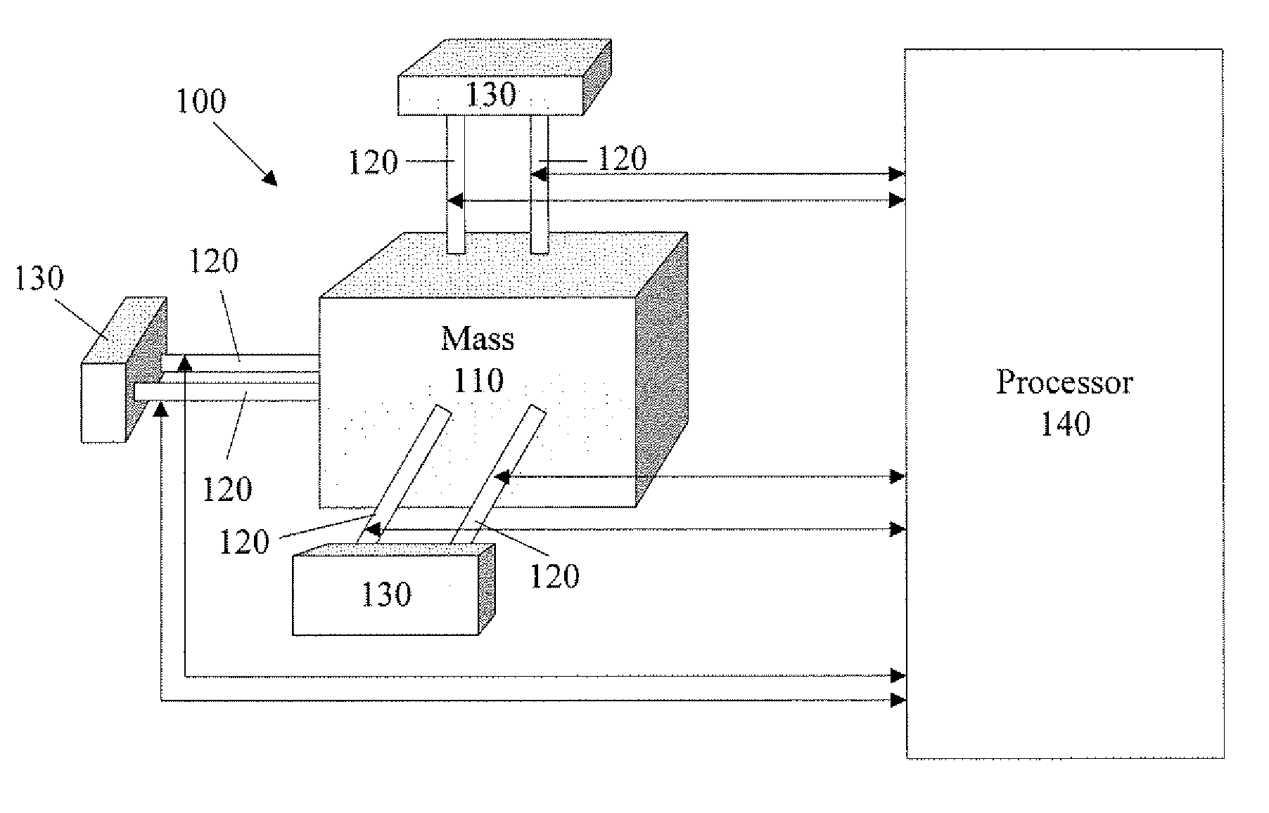
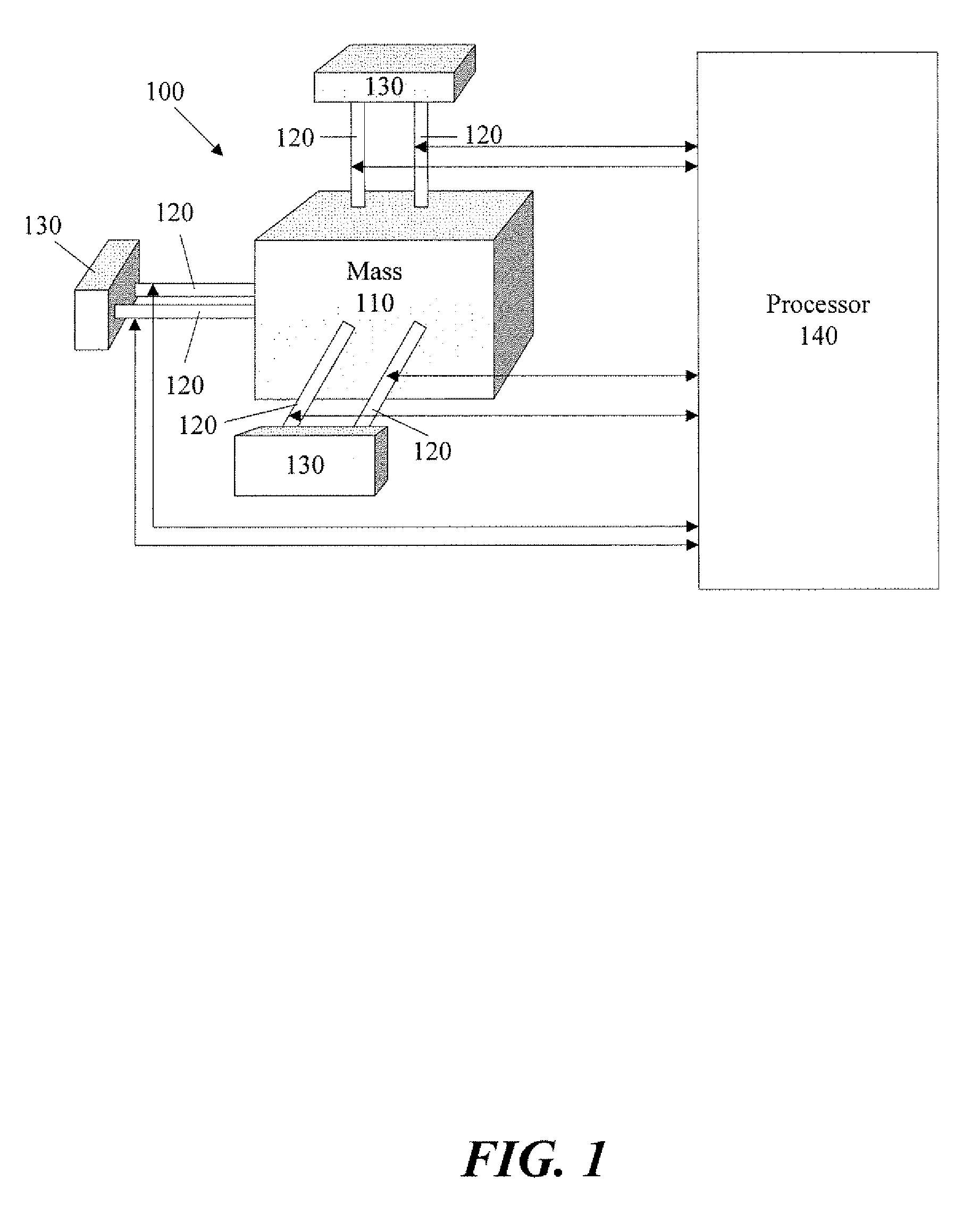
[0008]According to one exemplary embodiment of the invention, a method for calibrating a multiple-triad triaxial accelerometer is provided. This example method may include defining an objective function that includes one or more unknown calibration constants, and where the objective function accounts for at least alignment and rotation. The method may further include receiving accelerometer measured output for at least as many distinct positions as there are unknown calibration constants, and determining initial approximations for each of the unknown calibration constants. The method may additionally include optimizing output from the objective function, extracting one or more optimized calibration constants resulting from the optimization, and storing one or more of the optimized calibration constants associated with at least one calibration function in a controller associated with the multiple-triad triaxial...

Problems solved by technology

The errors may be the result of variances in the construction of the sensor elements, such as strain gauge variances or variances in the composition or output of individual force sensitive resonators.
Errors may also result from an inexact orientation of each sensor element in relation to the others and to the axes along which they are intended to be oriented.
However, averaging these individually-calibrated outputs may not produce the most accurate results.
Additionally, to correct for misalignment or inexact ...

Method used


Image

  • Systems and Methods for Calibrating Triaxial Accelerometers
  • Systems and Methods for Calibrating Triaxial Accelerometers
  • Systems and Methods for Calibrating Triaxial Accelerometers

Examples


Embodiment Construction

[0016]As used herein, the term “optimization” refers to the process of mathematical optimization, whereby the solution of at least one equation or at least one function (in some examples referred to as an objective function, as further described below) may be systematically solved in an effort to minimize or maximize (also referred to as “optimize”) the output of the equation or function. An “optimization” may be performed systematically or iteratively to solve for values of variables in the equation or function. It is appreciated that the term “optimization” is not intended to be limited to derive an absolute maximum solution or an absolute minimum solution, but may refer to the mathematical process of moving toward acceptable results. It is further appreciated that the term “optimum” refers to a condition, resulting from a mathematical optimization that meets system requirements. More specifically, for example, an “optimum” set of calibration constants (as further described below)...


PUM


Abstract

A method for calibrating a multiple-triad triaxial accelerometer is provided. The method may include receiving accelerometer measured output from a first measurement triad and at least one additional measurement triad of the accelerometer. The method may further include aligning the output of a x, y, and z components of the first measurement triad to be substantially orthogonal with respect to each other, aligning the output of x, y, and z components of at least one additional measurement triad to be substantially orthogonal with respect to each other, and rotating the output of at least one measurement triad so the outputs of all measurement triads substantially align with each other. The method may further include storing the result of the alignment and rotation associated with at least one calibration function associated with the multiple-triad triaxial accelerometer. The alignment and rotation may be performed substantially simultaneously.

Description

FIELD OF THE INVENTION[0001]The invention relates to accelerometers, and more particularly, to systems and methods for calibrating triaxial accelerometers.BACKGROUND OF THE INVENTION[0002]Generally, triaxial accelerometers produce output signals related to acceleration sensed in three linearly independent directions. More specifically, the triaxial accelerometer may include stress sensor elements intended to align with each of the three Cartesian coordinate axes. Thus, relative to each other, each stress sensor element may be configured to align in the x-axis, in the y-axis, and in the z-axis, respectively. The stress sensor elements may include force sensitive resonators, strain gauges, or the like, to allow measuring an output related to a change in position, a change in the load, or the like, of the inertial proof mass or other structure. The axial related output in an accelerometer (in three directions) may be referred to as a triad or a measurement triad.[0003]Some triaxial acc...

Claims


Application Information

Patent Timeline
IPC IPC(8): G01P21/00
CPCG01P21/00G01P15/18
Inventor STACHOW, ROBERTWOODMANSEE, MARK ALLENHAM, JEFFSEVEY, DAVID
Owner BAKER HUGHES INC
Why Eureka
Try Eureka