

Electron/hole transport-based NEMS gyro and devices using the same
a technology of nems gyro and electron/hole transport, applied in the field of gyroscopes, can solve the problems of large and often too expensive to be used in emerging applications, add to system complexity and cost, and have a great potential to significantly reduce fabrication costs
Inactive Publication Date: 2009-06-30
UT BATTELLE LLC
View PDF10 Cites 35 Cited by
- Summary
- Abstract
- Description
- Claims
- Application Information
AI Technical Summary
Benefits of technology
The patent describes a nanomechanical gyroscope that can detect angular velocity or acceleration. It includes an integrated circuit substrate, contact pads, and a movable element that forms a conductive path. The movable element experiences movement due to rotation or oscillation, which induces phase changes in current flow. The gyroscope can be used in an inertial measurement unit (IMU) that also includes an accelerometer for detecting acceleration and a GPS circuit for determining position. The technical effect of the patent is to provide a reliable and accurate sensor for detecting angular velocity and acceleration.
Problems solved by technology
Although, conventional rotating wheel, fiber optic and ring laser gyroscopes have dominated a wide range of applications, they are too large and often too expensive to be used in emerging applications.
Thus, there is great potential to significantly fabrication cost.
Although light-based Sagnac gyroscopes are suitable for certain applications, interfacing such interferometers with detectors and signal processors requires transduction which adds to system complexity and cost, and can also add errors.
Moreover, the inherent sensitivity provided by conventional Sagnac gyroscopes is not high enough for certain applications, such as high performance inertial measurement units (IMUs) needed for advanced navigation and guidance applications.
Method used
View moreImage
Smart ImageViewing Examples

Examples
examples
[0083]It should be understood that the Example described below is provided for illustrative purposes only and does not in any way define the scope of the invention.
[0084]FIG. 7 shows measured modulation data of electrical current resulting from oscillation of a gyroscope embodied as a suspended nanoconstriction responsive to irradiation by an actuating laser source. The electron current is shown by the solid curve. The sinusoidal modulated power waveform of the actuating laser source is shown by the dashed curve. The measured current is offset and normalized so that the average dc current is zero. It can be seen that the measured current exhibits a non-sinusoidal behavior thus evidencing a measurable phase shift.
Login to View More PUM
 Abstract
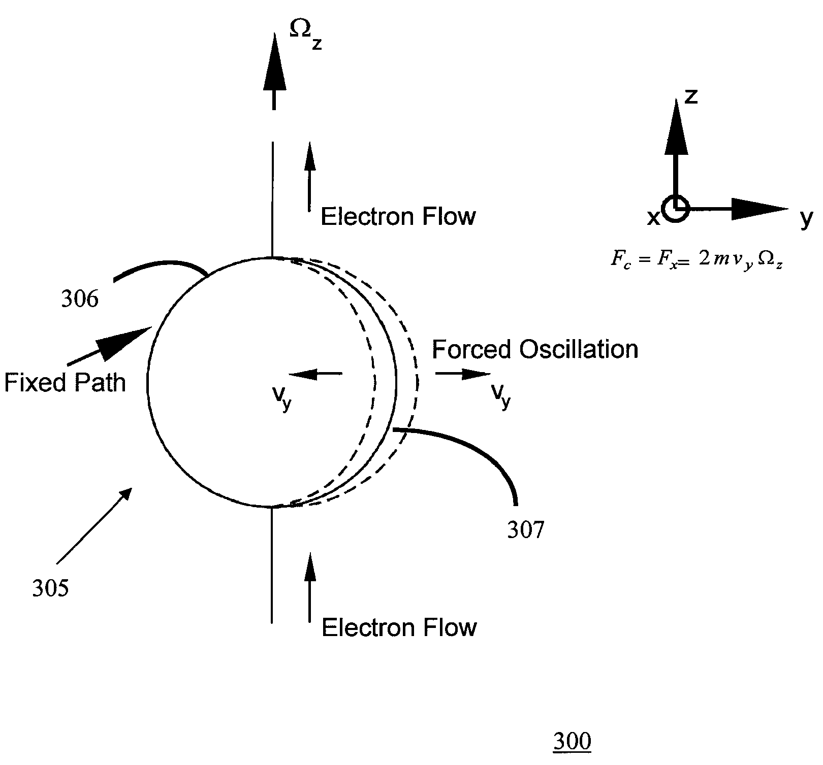
A nanomechanical (NEMS) gyroscope includes an integrated circuit substrate, a pair of spaced apart contact pads disposed on the substrate, and a movable nanoscale element forming at least a portion of a first electrically conductive path electrically coupling the contact pads. The movable element experiences movement comprising rotation, changes in rotation, or oscillation upon the gyroscope experiencing angular velocity or angular acceleration. Movement of the gyro introduces geometrically induced phase changes which results in phase and / or frequency changes in ac current flowing through the movable element. An inertial measurement unit (IMU) can include an integrated circuit substrate having a three axis gyroscope formed on the substrate and a three axis accelerometer, which is preferably formed on the same substrate.
Description
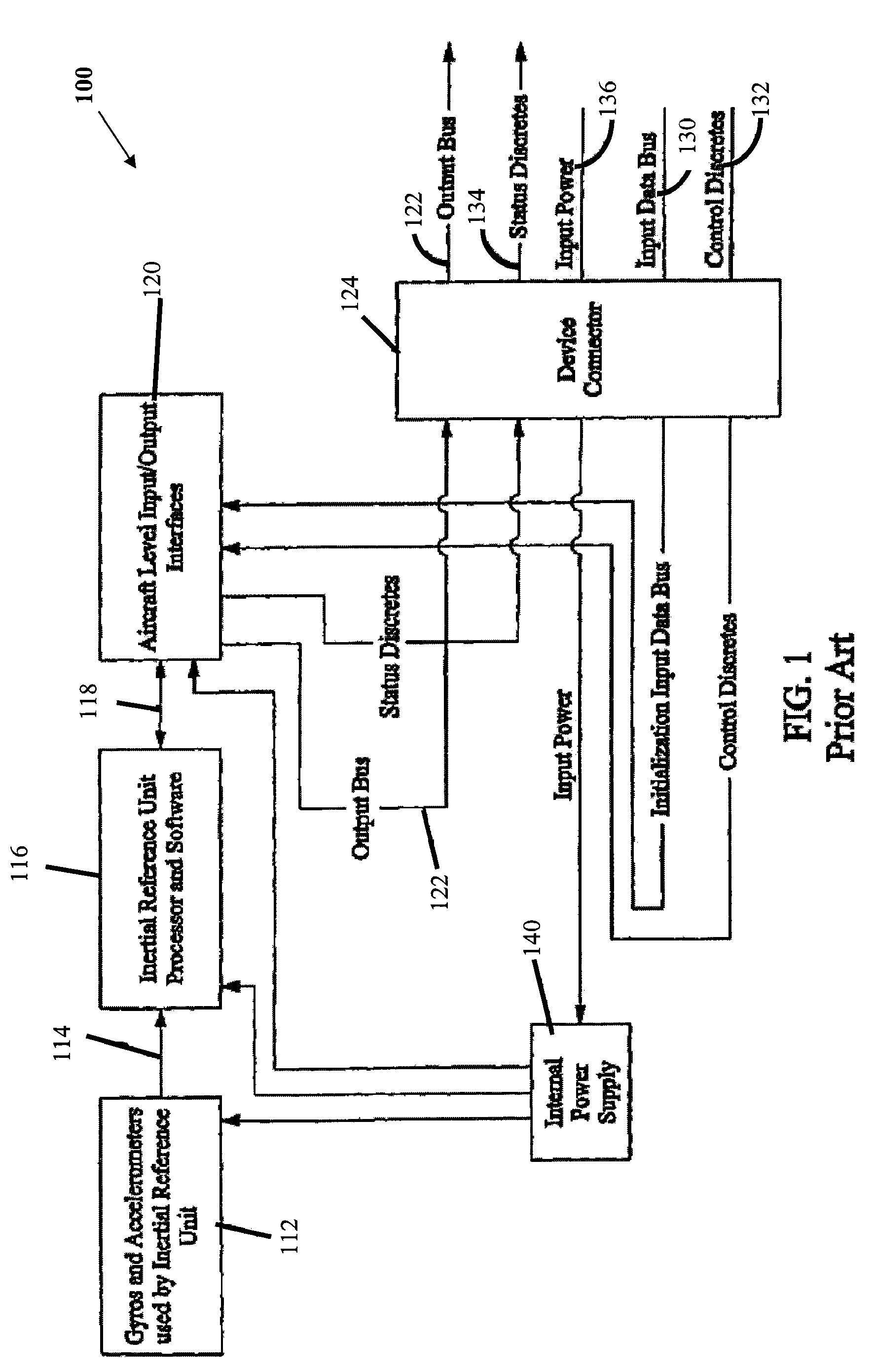
STATEMENT REGARDING FEDERALLY SPONSORED RESEARCH OR DEVELOPMENT[0001]The United States Government has rights in this invention pursuant to Contract No. DE-AC05-00OR22725 between the United States Department of Energy and UT-Battelle, LLC.CROSS-REFERENCE TO RELATED APPLICATIONS[0002]Not applicable.FIELD OF THE INVENTION[0003]The invention relates to gyroscopes and more particularly gyroscopes based on electron or hole propagation through solid state media.BACKGROUND OF THE INVENTION[0004]Gyroscopes are commonly used as sensors for measuring angular velocity in many applications including navigation and guidance, as well as for control stabilization. Although, conventional rotating wheel, fiber optic and ring laser gyroscopes have dominated a wide range of applications, they are too large and often too expensive to be used in emerging applications. Navigation and guidance systems generally utilize gyroscopes together with accelerometers.[0005]FIG. 1 is a block diagram of a known inert...
Claims
Login to View More Application Information
Patent Timeline
 Patent Type & AuthorityPatents(United States)
IPC IPC(8): G01P3/44G01P3/00
CPCB82Y15/00G01C19/56G01C19/5719
InventorDATSKOS, PANOS
OwnerUT BATTELLE LLC