Tri-axis accelerometer

a tri-axis accelerometer and accelerometer technology, applied in the field of microelectromechanical systems (mems) accelerometers, can solve the problems of temperature and package sensitive, and the detection of acceleration by a mems accelerometer may be affected by changes, so as to achieve less temperature and package sensitive effects

Active Publication Date: 2008-10-07
ROHM CO LTD
View PDF12 Cites 37 Cited by
  • Summary
  • Abstract
  • Description
  • Claims
  • Application Information

AI Technical Summary

Problems solved by technology

A problem with current MEMS accelerometers is that they are temperature and package sensitive.
That is, the detection of an acceleration by a MEMS accelerometer may be affected by changes in temperature and / or by stresses imposed on the packaging unit.

Method used


Image

  • Tri-axis accelerometer
  • Tri-axis accelerometer
  • Tri-axis accelerometer

Examples


example tri -

Example Tri-Axis Accelerometer Embodiments

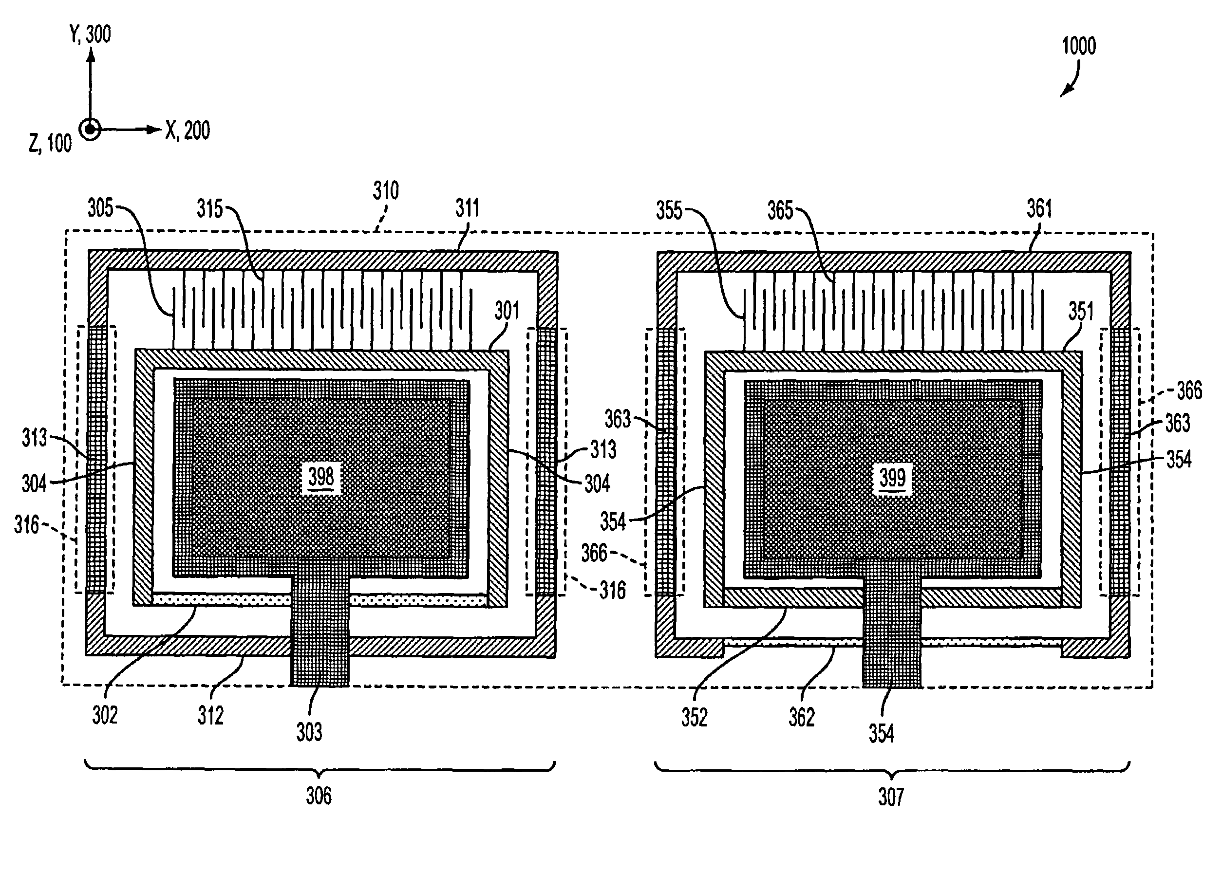
[0059]FIGS. 10A and 11 illustrate example design concepts for tri-axis accelerometers in accordance with embodiments of the present invention. One significant difference between these designs and designs presented above is that the z-sense element halves are effectively supported at single points. By effectively supporting a z-sense element at a single point, output shifts due to package stresses and temperature changes are substantially reduced. Early experiments have shown approximately a 5× reduction in temperature sensitivity and a 10× reduction in package stress induced output shifts. In addition to the improvement in performance, the design concepts schematically illustrated in FIGS. 10A and 11 also have permitted a 40% reduction in area required for the sense element, effectively lowering the cost of production by a similar percentage.

[0060]Although the supports are described as “single point,” the supports can have some small separat...


PUM


Abstract

In an embodiment of the present invention there is provided a micro-electromechanical (MEMS) accelerometer, including a substrate, a first sensor and a second sensor. The first sensor is configured to measure an acceleration along a first axis parallel to a plane of the substrate. The second sensor is configured to measure an acceleration along an axis perpendicular to the plane of the substrate. The second sensor comprises a first beam, a second beam and a single support structure. The single support structure supports the first and second beams relative to the substrate, wherein the first and second beams circumscribe the first sensor.

Description

CROSS REFERENCE TO RELATED APPLICATIONS[0001]This application claims benefit under 35 U.S.C. § 119(e) to U.S. Provisional Patent Application 60 / 738,580, entitled “A Tri-Axis Accelerometer,” to Adams et al., filed on Nov. 22, 2005, the entirety of which is hereby incorporated by reference as if fully set forth herein.BACKGROUND OF THE INVENTION[0002]1. Field of the Invention[0003]The present invention is directed generally to micro-electromechanical systems (MEMS) accelerometers.[0004]2. Background Art[0005]An accelerometer is a device that measures an acceleration. Using MEMS technology, an accelerometer can be fabricated on a (silicon) substrate. Accelerometer elements constructed using MEMS include structures similar to a standard accelerometer: a proof-mass, restoring springs, a displacement transducer, some form of damping, and a case to which everything is attached.[0006]For example, FIG. 1A illustrates an example accelerometer with a few features specific to a subset of MEMS a...

Claims


Application Information

Patent Timeline
Patent Type & Authority Patents(United States)
IPC IPC(8): G01P15/125
CPCG01P15/0802G01P15/125G01P15/18G01P2015/0828G01P15/00
Inventor ADAMS, SCOTT G.MILLER, SCOTT A.SHEN-EPSTEIN, JUNEEPSTEIN, KEITH
Owner ROHM CO LTD
Why Eureka
Try Eureka