Waste liquid collector

Active Publication Date: 2009-09-03
SEIKO EPSON CORP
View PDF2 Cites 18 Cited by
  • Summary
  • Abstract
  • Description
  • Claims
  • Application Information

AI Technical Summary

Benefits of technology

[0027]With such a configuration, the guide unit is formed with the simple configuration in which the groove or the hole is cut i

Problems solved by technology

Here, an absorption capability of the waste ink absorbing member is limited.
Therefore, when the absorption capability reaches the limit, an absorption efficiency of the waste ink may decrease.
Therefore, when the discharge unit is extracted from the opening, the attached waste ink

Method used


Image

  • Waste liquid collector
  • Waste liquid collector
  • Waste liquid collector

Examples


first embodiment

[0055]Hereinafter, an ink jet printer which is an example of a liquid ejecting device including a waste liquid collecting system in which a waste liquid collector according to the invention is detachably mounted will be described with reference to FIGS. 1 to 11 according to a first embodiment. “Front and rear directions”, “upper and lower directions”, and “right and left direction” in the following description refer to “front and rear directions”, “upper and lower directions”, and “right and left direction” indicated by arrows in FIGS. 1 to 3, unless particularly mentioned.

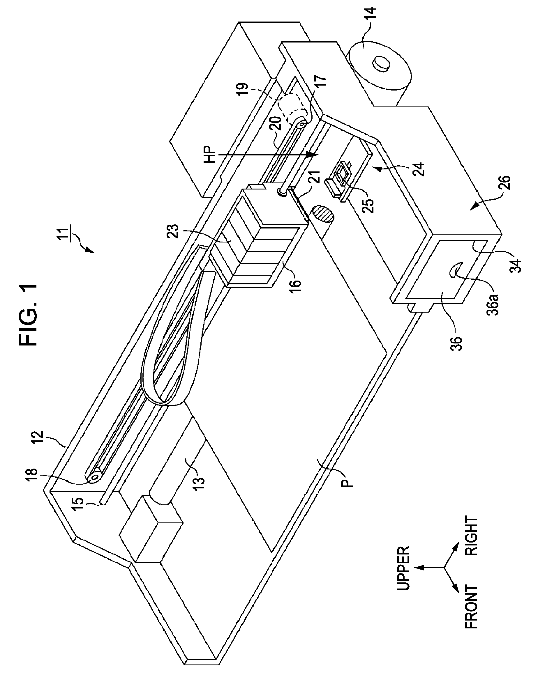
[0056]As shown in FIG. 1, an ink jet printer (hereinafter, referred to as “a printer) 11 as a liquid ejecting device according to this embodiment includes a frame 12 having a rectangular shape in plan view. A platen 13 extends in the right and left direction inside the frame 12. A sheet-feeding mechanism which is disposed above the platen 13 and includes a sheet-feeding motor 14 feeds a print sheet P from the rear...

second embodiment

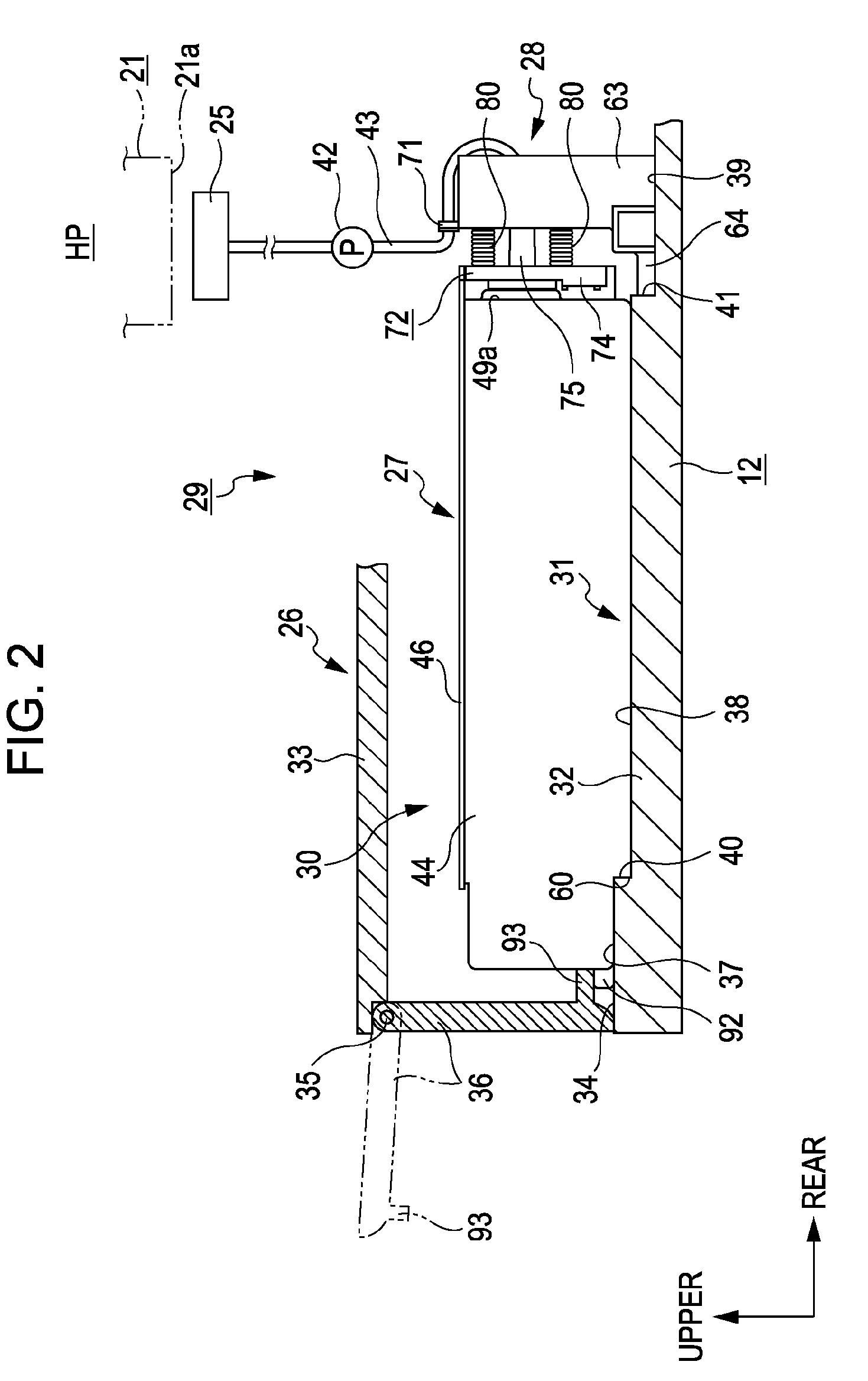
[0167]Next, a second embodiment of the invention will be described with reference to FIG. 12. In the second embodiment, since only a formation location of the air communication hole 90 is different from that in the first embodiment and the other configuration is the same, the air communication hole 90 will be mainly described below. In addition, the same reference numerals are given to the same constituent elements and repeated description is omitted.

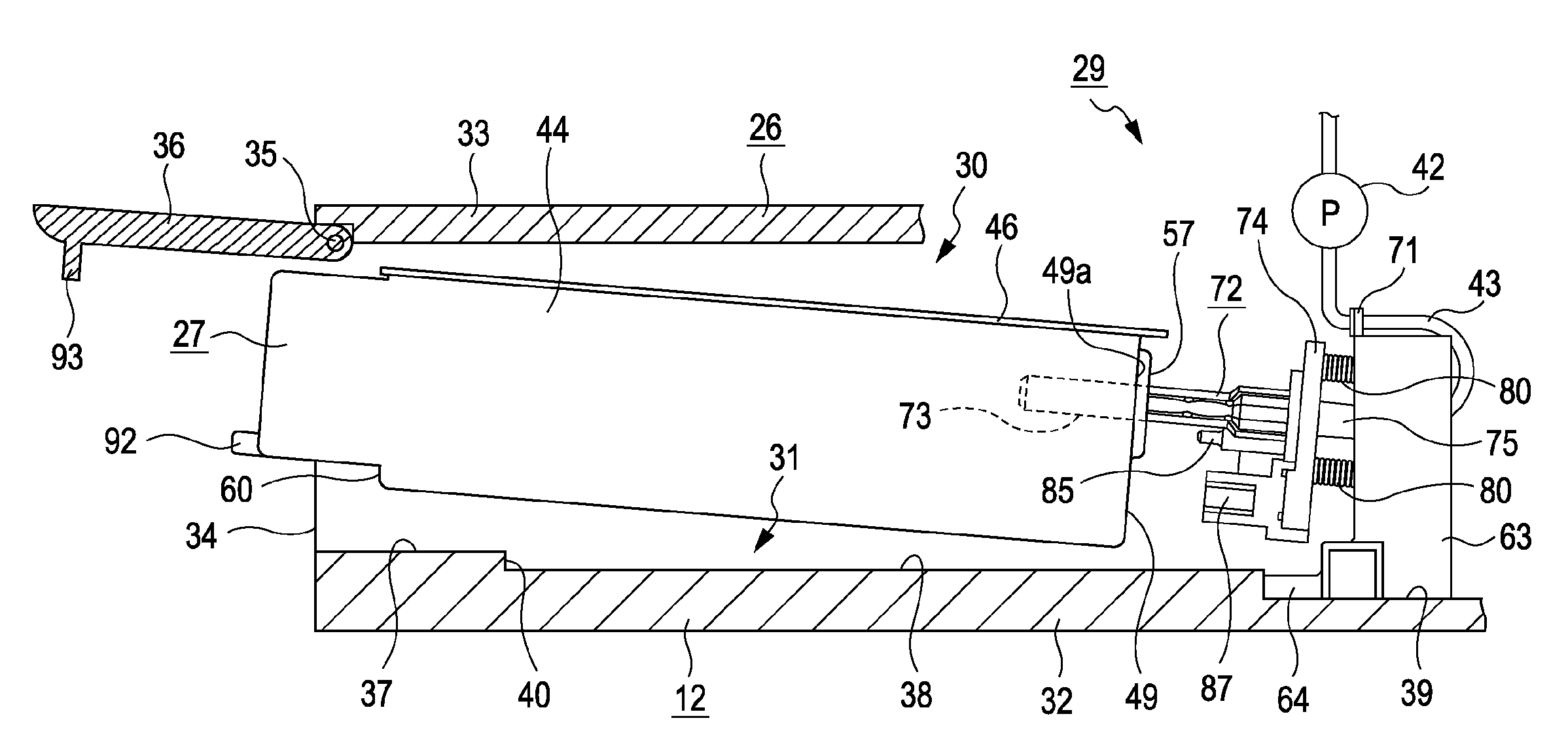
[0168]In the waste ink tank 27 according to this embodiment, as shown in FIG. 12, the air communication hole 90 is formed at the substantially center in the longitudinal direction of the film member 46. In addition, when the discharge unit 97 of the cylindrical body 73 is inserted into the container member 44 from the connection port 57 of the waste ink tank 27, a distance Y between the front end opening 76a and the air communication hole 90 is configured to be shorter than a distance X between the connection port 57 and the front end o...

third embodiment

[0207]Hereinafter, an ink jet printer which is an example of a liquid ejecting device including a waste liquid collecting system in which a waste liquid collector according to the invention is detachably mounted will be described with reference to FIGS. 1 to 11 according to a first embodiment. “Front and rear directions”, “upper and lower directions”, and “right and left direction” in the following description refer to “front and rear directions”, “upper and lower directions”, and “right and left direction” indicated by arrows in FIGS. 1 to 3, unless particularly mentioned.

[0208]As shown in FIG. 1, an ink jet printer (hereinafter, referred to as “a printer) 11 as a liquid ejecting device according to this embodiment includes a frame 12 having a rectangular shape in plan view. A platen 13 extends in the right and left direction inside the frame 12. A sheet-feeding mechanism which is disposed above the platen 13 and includes a sheet-feeding motor 14 feeds a print sheet P from the rear...


PUM

PropertyMeasurementUnit
Gravityaaaaaaaaaa

Abstract

A waste liquid collector is detachably mounted on a device including a discharge unit discharging a waste liquid and stores the waste liquid discharged from the discharge unit when the waste liquid collector is mounted on the device. The waste liquid collector includes: a waste liquid absorbing member which absorbs the waste liquid; and an opening through which the discharge unit is inserted or extracted mounting or detaching the waste liquid collector on or from the device in a state where the waste liquid absorbing member is received inside an inner space. The waste liquid absorbing member is provided with a contact portion which, when the discharge unit is inserted into the opening, comes in contact with the discharge unit so that the discharge unit is interposed therebetween in a direction perpendicular to insertion and extraction directions of the discharge unit.

Description

CROSS REFERENCE TO RELATED APPLICATIONS[0001]The entire disclosure of Japanese Patent Application Nos. 2008-119192, filed Apr. 30, 2008, 2008-119193, filed Apr. 30, 2008, 2008-119194, filed Apr. 30, 2008, 2008-049542, filed Feb. 29, 2008, 2008-049543, filed Feb. 29, 2008, 2008-049541, filed Feb. 29, 2008 are expressly incorporated by reference herein.BACKGROUND[0002]1. Technical Field[0003]The present invention relates to a waste liquid collector which is detachably mounted on a device which includes a discharge unit discharging a waste liquid and is capable of storing the waste liquid discharged from the discharge unit when being mounted on the device.[0004]2. Related Art[0005]In the past, as a liquid ejecting device which ejects a liquid to a target from nozzle openings formed in a liquid ejecting head, an ink jet printer (hereinafter, simply referred to as “a printer”), for example, was well known. In this printer, a so-called cleaning process of forcedly sucking thickened ink wi...

Claims


Application Information

Patent Timeline
IPC IPC(8): B01D29/00
CPCB41J2/16523B41J2002/1728B41J2/1721
Inventor HARADA, SHUHEI
Owner SEIKO EPSON CORP
Why Eureka
Try Eureka