

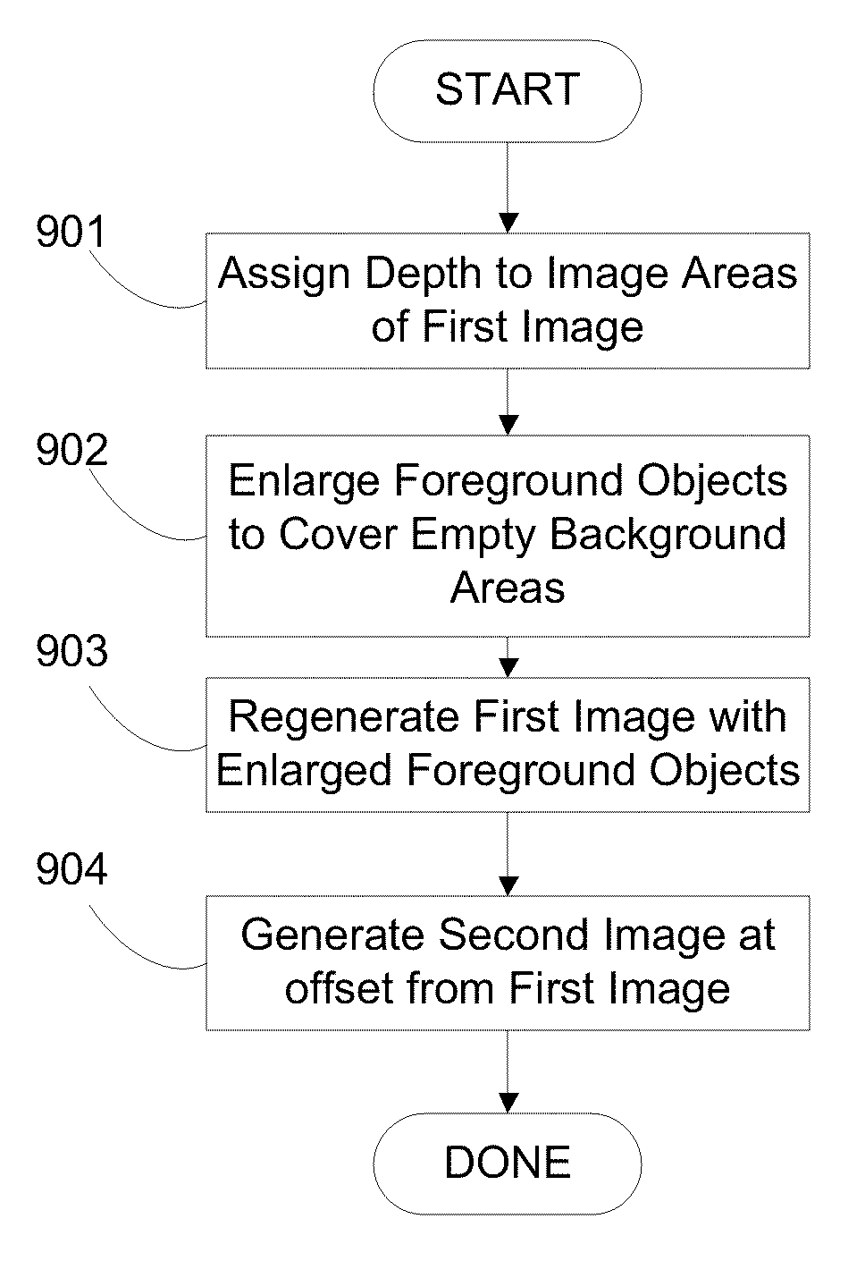
Image depth augmentation system and method
a depth augmentation and depth technology, applied in the field of computer systems, can solve problems such as poor scene impression, achieve the effects of preventing scintillation, reducing the amount of enlargement needed, and reducing the amount of enlargemen
- Summary
- Abstract
- Description
- Claims
- Application Information
AI Technical Summary
Benefits of technology
Problems solved by technology
Method used
Image

Examples
Embodiment Construction
[0036]An image depth augmentation system and method for providing three-dimensional views of a two-dimensional image will now be described. In the following exemplary description numerous specific details are set forth in order to provide a more thorough understanding of embodiments of the invention. It will be apparent, however, to an artisan of ordinary skill that the present invention may be practiced without incorporating all aspects of the specific details described herein. In other instances, specific features, quantities, or measurements well known to those of ordinary skill in the art have not been described in detail so as not to obscure the invention. Readers should note that although examples of the invention are set forth herein, the claims, and the full scope of any equivalents, are what define the metes and bounds of the invention.
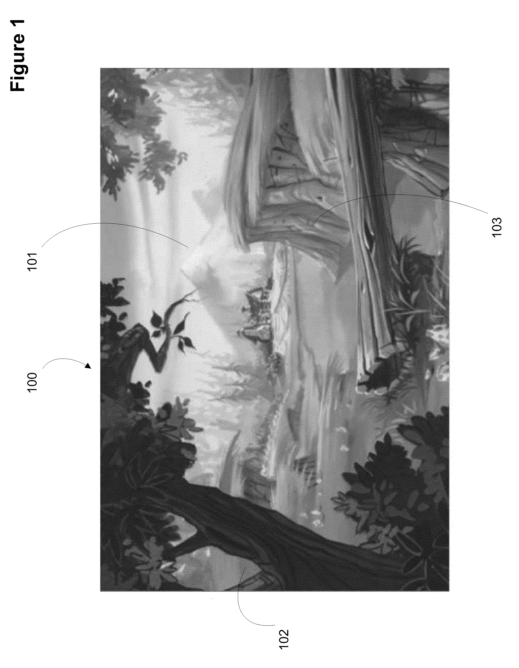
[0037]FIG. 1 shows single image 100 to be augmented for three-dimensional viewing. In this image, the human mind interprets hazy mountains 1...
PUM
 Abstract
Description
Claims
Application Information