Interface for Building a Print Container

a printing container and user interface technology, applied in the direction of digital output to print units, instruments, digital computers, etc., can solve the problems of loss of distinct fixed documents used to create the merged print container, inability to provide the print container to the user, and merging of print settings

Active Publication Date: 2009-09-03
SHARP KK
View PDF7 Cites 27 Cited by
  • Summary
  • Abstract
  • Description
  • Claims
  • Application Information

AI Technical Summary

Benefits of technology

[0028]Additional details of the above-described method are described in more detail below.

Problems solved by technology

Normally, the act of printing streams the print container to a spooler or directly to the printer, and the print container is not available to the user.
One problem with the merged print container is the loss of distinct fixed documents used to create the merged print container.
An additional issue is the merging of print settings.
Another issue in conventional printing is that electronic documents often appear one way when viewed on a monitor screen and another way when printed.
Unfortunately, there is no guarantee that users with different printers attached to different machines will see the exact same document printed on paper as when the document is viewed on the monitor screen.
The problem is that, at present, there is no convenient way to combine a set of such documents into a single XPS container (file).
However, the task is awkward and subject to errors.
Also, doing this task manually makes the inclusion of print tickets for the entire container (job level), the specific documents (document level), and within specific sections of a specific document difficult to accomplish.
Lastly, it is unclear whether such capability will include accessing specific files within the XPS container, to add print ticket options without the applications used to originally create the documents.

Method used


Image

  • Interface for Building a Print Container
  • Interface for Building a Print Container
  • Interface for Building a Print Container

Examples


Embodiment Construction

[0037]Various embodiments are now described with reference to the drawings. In the following description, for purposes of explanation, numerous specific details are set forth in order to provide a thorough understanding of one or more aspects. It may be evident, however, that such embodiment(s) may be practiced without these specific details. In other instances, well-known structures and devices are shown in block diagram form in order to facilitate describing these embodiments.

[0038]As used in this application, the terms “processor”, “processing device”, “component,”“module,”“system,” and the like are intended to refer to a computer-related entity, either hardware, firmware, a combination of hardware and software, software, or software in execution. For example, a component may be, but is not limited to being, a process running on a processor, a processor, an object, an executable, a thread of execution, a program, and / or a computer. By way of illustration, both an application runn...


PUM


Abstract

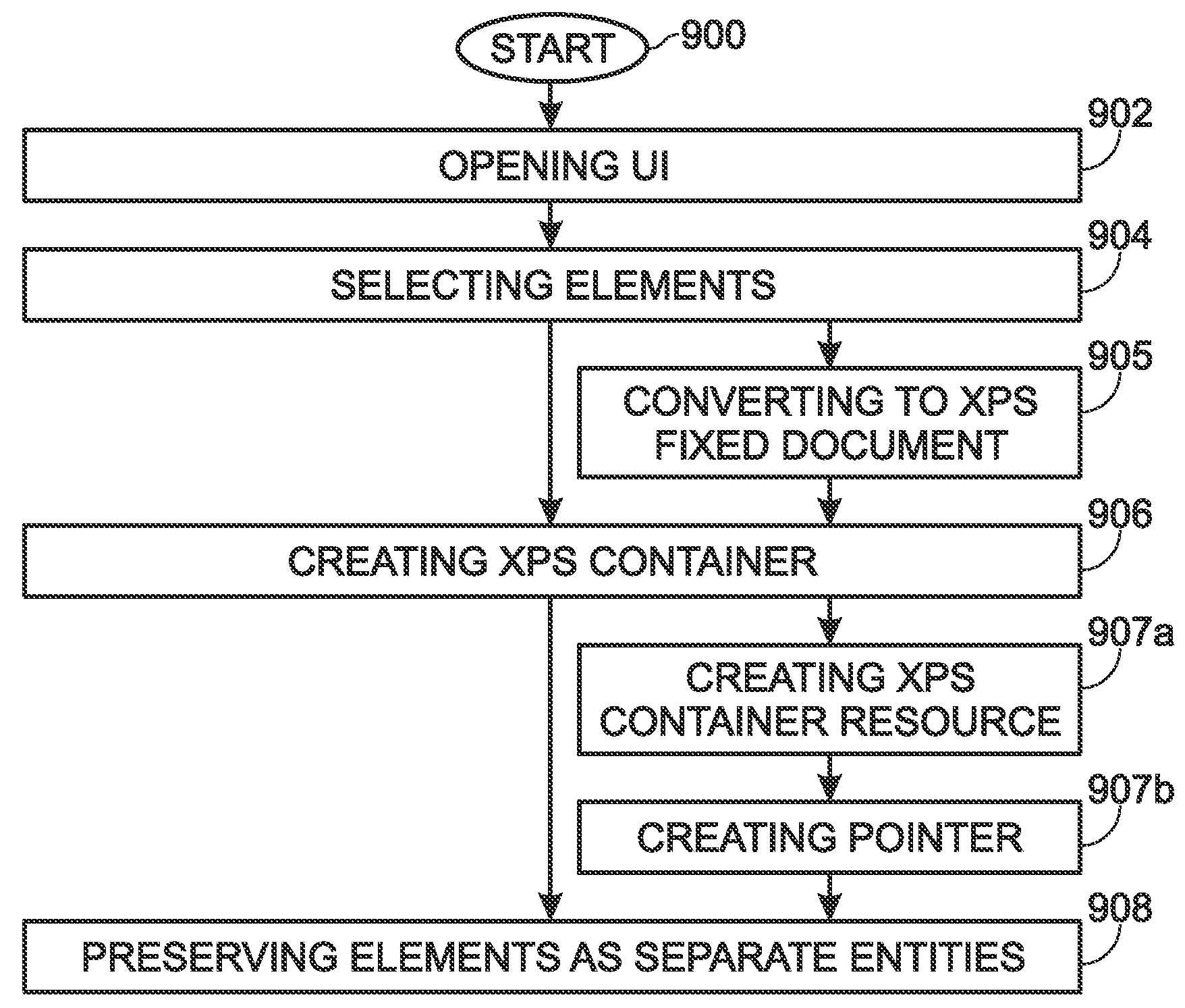
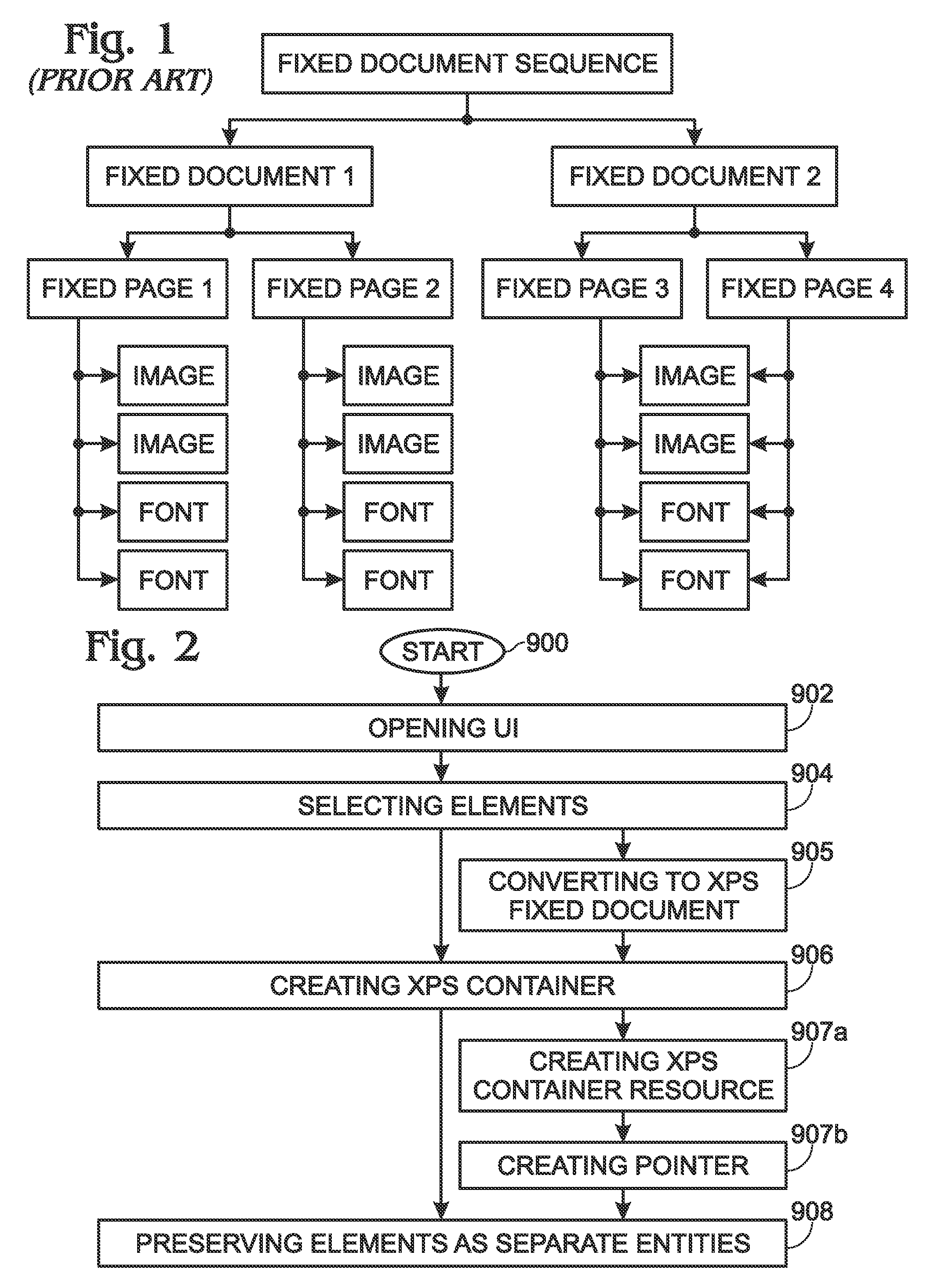
A method is provided for creating a print container with a series of resident fixed documents. The method opens a user interface (UI). Using the UI, a first plurality of elements stored in memory is selected and a print container is created. The print container preserves a second plurality of elements as separate entities in the print container. For example, a print container may have an element hierarchy of jobs in the print container, fixed documents in a job, and fixed pages in a fixed document may be created. Elements are defined as print containers, fixed documents, application-specific documents, page description language (PDL) documents, extensible markup language (XML) paper specification (XPS) fixed documents, or combinations of the above-mentioned elements. In one aspect, the selected elements are extensible markup language (XML) paper specification (XPS) fixed documents, which are preserved as separate entities in an XPS container.

Description

BACKGROUND OF THE INVENTION[0001]1. Field of the Invention[0002]This invention generally relates to printer driver software and, more particularly, to a print driver with a user interface for building a print container that preserves separate elements.[0003]2. Description of the Related Art[0004]Conventional methods exist for combining print containers into a single print container. Applications such as SharpDesk™ allow the user to print any document and save the resulting commands as a print container (i.e., a SharpDesk™ document). SharpDesk™ then allows the user to view all such print containers. A useful function in SharpDesk™ consists of combining the print containers into new print containers. This function allows a user to combine related print containers into a single print container that can be printed or sent as email or used in many in document management functions.[0005]More generally, each act of printing involves a single application printing a single document producing...

Claims


Application Information

Patent Timeline
Patent Type & Authority Applications(United States)
IPC IPC(8): G06F3/12G06F3/048G06F3/0487
CPCG06F3/1253G06F3/1205
Inventor LEVIN, BURTON LEEOWEN, JAMES E.JOHNSON, ALEX LANE
Owner SHARP KK
Why Eureka
Try Eureka