
Method for transmitting and receiving signals using multi-band radio frequencies

a multi-band radio and transmitting frequency technology, applied in the field of transmitting and receiving signals, to achieve the effect of reducing papr, facilitating procedure, and efficient management of carrier frequency bands

Active Publication Date: 2009-09-03
LG ELECTRONICS INC
View PDF18 Cites 60 Cited by
  • Summary
  • Abstract
  • Description
  • Claims
  • Application Information

AI Technical Summary

Benefits of technology

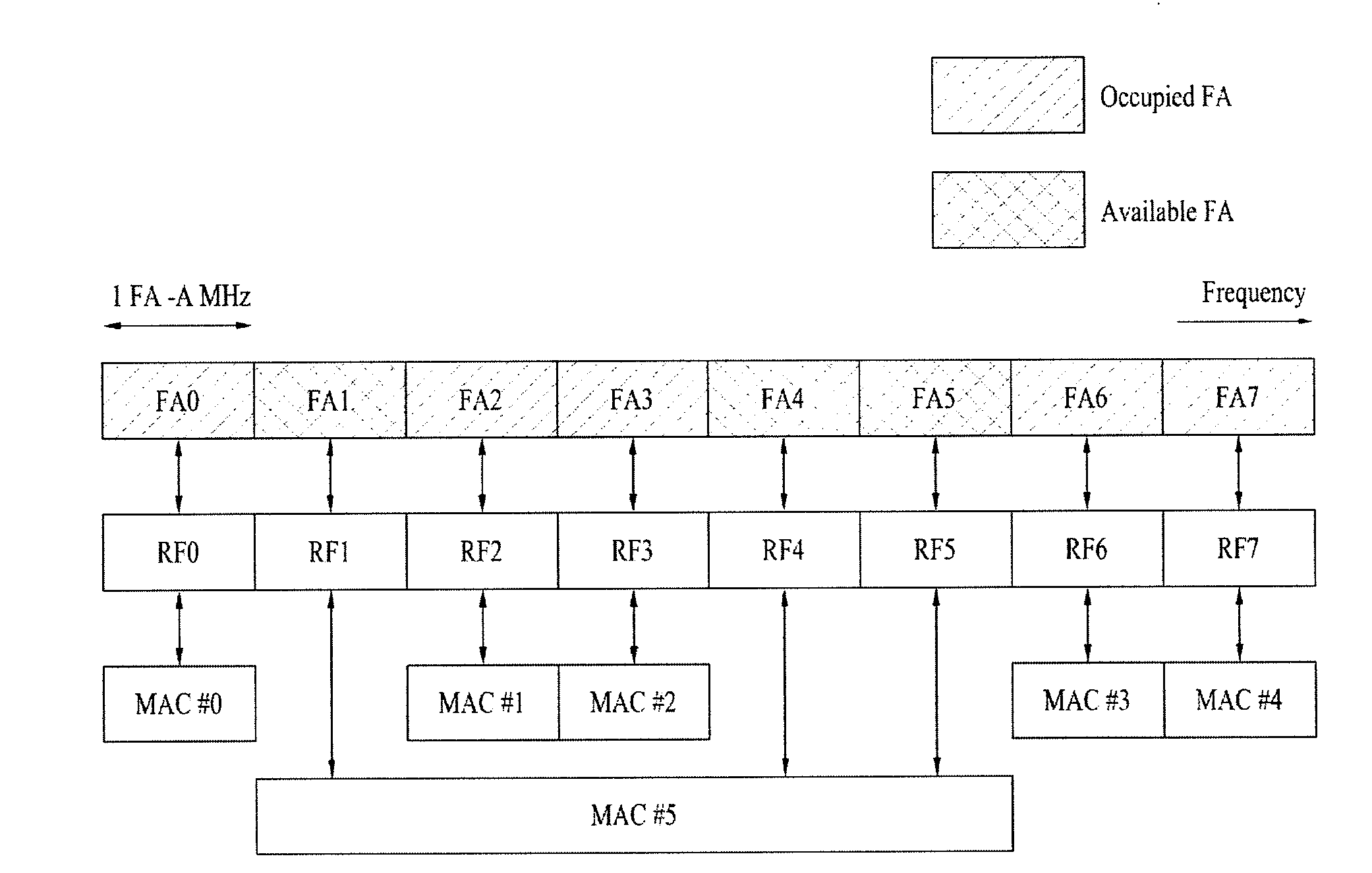
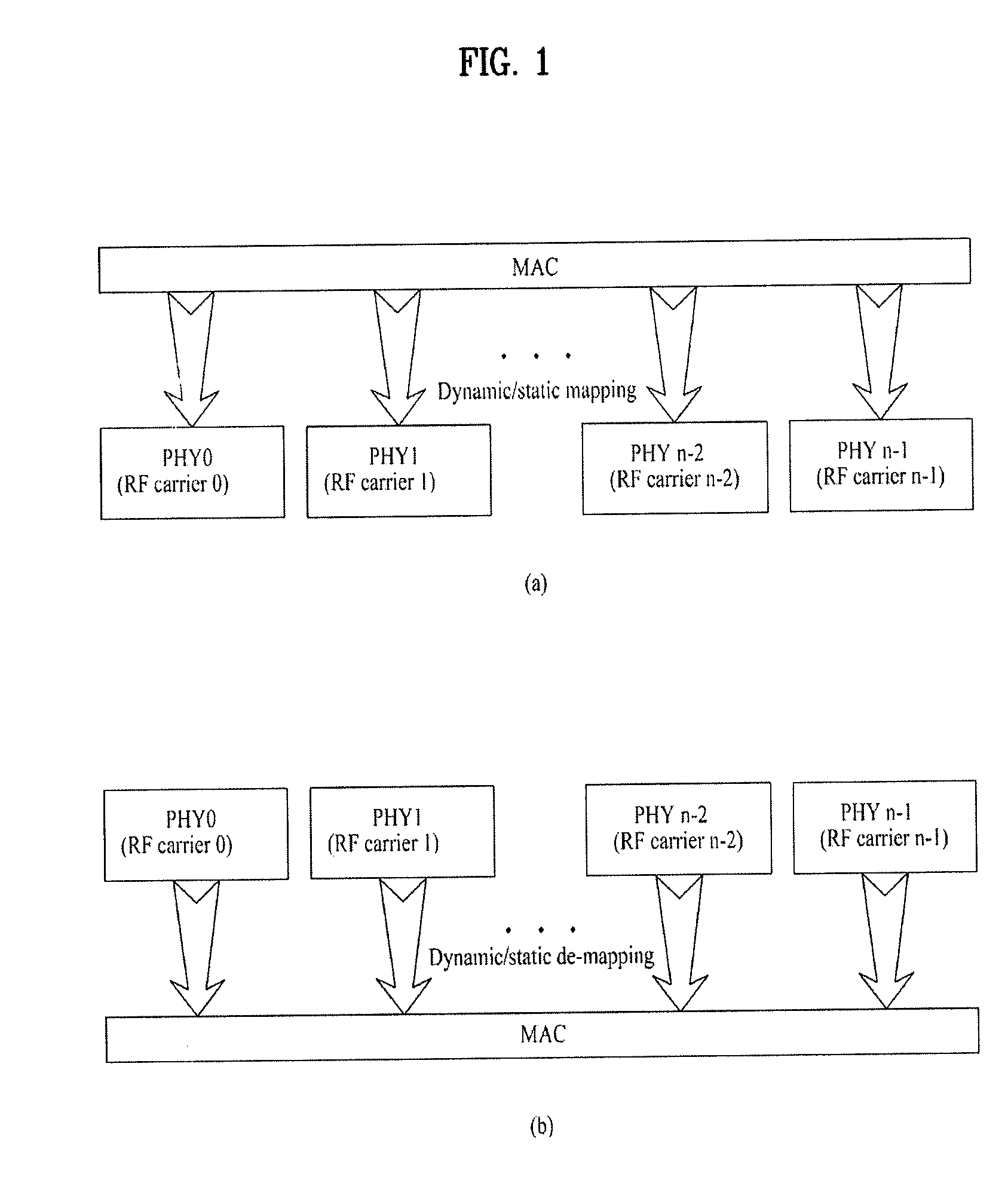
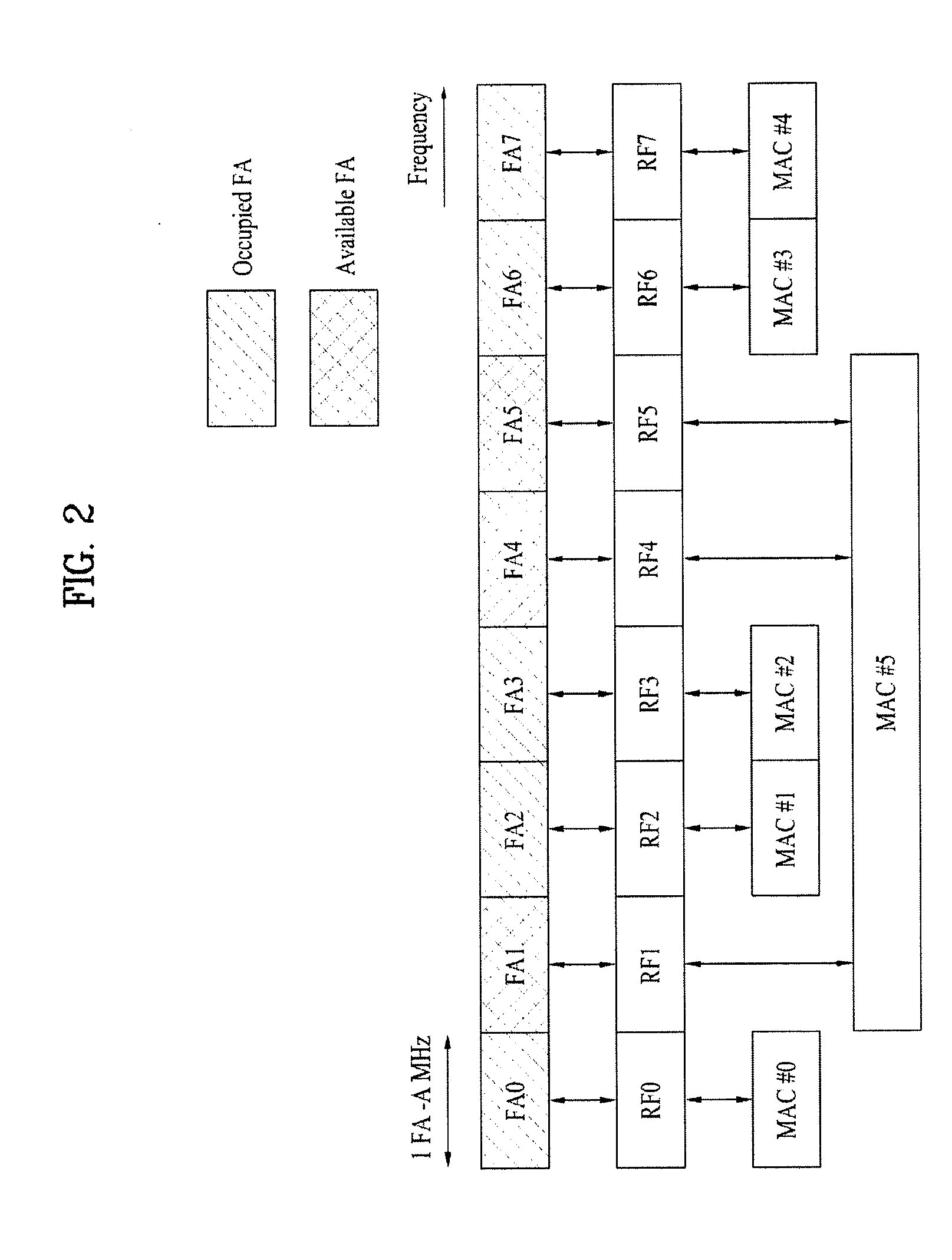
[0021]An object of the present invention devised to solve the problem lies on providing a method for transmitting and receiving signals, wherein ID information of multiple frequency bands is specified in a multi-band-based communication system and a method for efficiently signaling ID-related information to achieve improved signal transmission and reception.
[0029]According to each of the embodiments of the present invention described above, it is possible to more efficiently manage a plurality of carrier frequency bands managed by one entity and the receiving side can more easily set a procedure for receiving signals through a plurality of carriers.
[0030]In addition, according to the embodiment wherein a timing offset is applied to the entirety of a frame or to a preamble (synchronous channel) transmitted in the frame, it is possible to distribute the time of signal transmission, thereby reducing the PAPR.

Problems solved by technology

However, the above multi-band-based communication scheme has only been conceptually defined and an ID specification method, which enables more efficient management of each frequency allocation band, and a method for signaling ID-related information have not been defined in detail.

Method used


Image

  • Method for transmitting and receiving signals using multi-band radio frequencies
  • Method for transmitting and receiving signals using multi-band radio frequencies
  • Method for transmitting and receiving signals using multi-band radio frequencies

Examples


Embodiment Construction

[0044]Reference will now be made in detail to the preferred embodiments of the present invention with reference to the accompanying drawings. The detailed description, which will be given below with reference to the accompanying drawings, is intended to explain exemplary embodiments of the present invention, rather than to show the only embodiments that can be implemented according to the invention.

[0045]The following detailed description includes specific details in order to provide a thorough understanding of the present invention. However, it will be apparent to those skilled in the art that the present invention may be practiced without such specific details. In some instances, known structures and devices are omitted or are shown in block diagram form, focusing on important features of the structures and devices, so as not to obscure the concept of the present invention. The same reference numbers will be used throughout this specification to refer to the same or like parts.

[00...


PUM


Abstract

A method for transmitting and receiving signals using multi-band Radio Frequencies (RFs) is provided. The method transmits an information unit of a specific layer above a physical layer through a plurality of frequency allocation bands managed by the specific layer and transmits control information identifying each of the plurality of frequency allocation bands. The control information identifying each of the plurality of frequency allocation bands includes a second ID into which a first ID has been converted, the first ID identifying each of the plurality of frequency allocation bands in the physical layer, the second ID identifying each of the plurality of frequency allocation bands managed by the specific layer in the specific layer. To accomplish this, a timing offset is applied to the entirety of a frame or to a preamble (synchronous channel) so that the timing offset is used as the ID. Applying a timing offset to the entirety of a frame or to a preamble (synchronous channel) can achieve an advantage of PAPR reduction.

Description

CROSS-REFERENCE TO RELATED APPLICATIONS[0001]This application claims the benefit of the U.S. Provisional Application No. 61 / 016,799, filed on Dec. 26, 2007, which is hereby incorporated by reference as if fully set forth herein.[0002]This application claims the benefit of the Korean Patent Application Nos. 10-2008-0025817, 10-2008-0075554, 10-2008-0084731 and 10-2008-0096055, filed on Mar. 20, 2008, Aug. 1, 2008, Aug. 28, 2008 and Sep. 30, 2008, respectively, which are hereby incorporated by reference as if fully set forth herein.BACKGROUND OF THE INVENTION[0003]1. Field of the Invention[0004]The present invention relates to a method for transmitting and receiving signals, wherein multi-band IDs are specified in order to efficiently manage multi-band Radio Frequencies (RFs) in a communication system that supports multi-band RFs and ID-related information is signaled to transmit and receive signals.[0005]2. Discussion of the Related Art[0006]The following description is given mainly ...

Claims


Application Information

Patent Timeline
IPC IPC(8): H04J1/02
CPCH04L27/2614H04J11/0069H04W72/0453H04W74/002H04W80/02H04W88/02H04W88/08H04L1/0023H04L1/0031H04L5/0053H04L69/323H04W72/23H04W72/21
Inventor HAN, SEUNG HEECHUN, JIN YOUNGLEE, WOOK BONGNOH, MIN SEOKKWAK, JIN SAMKWON, YEONG HYEONLEE, HYUN WOOCHOI, JIN SOOKIM, DONG CHEOLMOON, SUNG HOIHM, BIN CHULLEE, MOON II
Owner LG ELECTRONICS INC
Learn More