Partial Printing Of A Substrate Using Metallization

Inactive Publication Date: 2009-09-03
CONTRA VISION
View PDF16 Cites 18 Cited by
  • Summary
  • Abstract
  • Description
  • Claims
  • Application Information

AI Technical Summary

Benefits of technology

[0060](iii) The provision of a metallized layer, for example in a print pattern of lines or interconnected elements, provides a layer of much greater thermal conductivity than the glass or any applied film, adhesive or ink, enabling the transfer of absorbed heat from one area to another within a glass lite or pane, thus reducing any differential thermal expansion that would otherwise occur. Conventional window graphic systems have been associated with a number of glass fracture incidents thought to have been caused by differential solar thermal heating of windows in differently colored areas. Darkly coloured areas absorb more heat than lighter colored areas, causing differential thermal expansion stresses which have on occasion caused glass breakage, perhaps initiated at points of relative weakness in the glass, for example by impurity inclusions in the glass. Even without any applied graphics, glass is known to suffer spontaneous failure through temperature change, including tempered (toughened) glass. While aluminium metallization is typically adopt

Problems solved by technology

This variable thickness of relatively thick ink layers exacerbates “under-etch” and “over-etch”, which are known problems with any resist and etch method.
This method has an additional disadvantage when using solvent inks that obtain their bond partly or totally through an etching action into a transparent substrate.
When this ink is removed, the surface is no longer plane but has a surface topography which may be sufficiently pitted to cause optical distortion, preventing proper focusing upon an object on the other side of the transparent substrate.
There are known problems of solvent migration from one ink layer to other ink layers, which affects the efficiency of these resist, direct and stencil processes including, for example, making it difficult to subsequently remove unwanted ink and/or causing interaction of colored ink layers, causing a “ghost image” of the design to be visible from the other side of the panel and/or deleteriously affecting the light permeable material and/or an adhesive layer on the other side of the light permeable material.
However, none of the prior art discloses a metallic layer as part of the production process to achieve desired

Method used


Image

  • Partial Printing Of A Substrate Using Metallization
  • Partial Printing Of A Substrate Using Metallization
  • Partial Printing Of A Substrate Using Metallization

Examples


Example

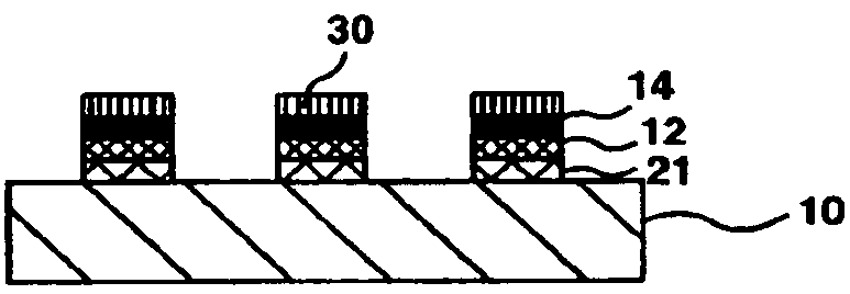
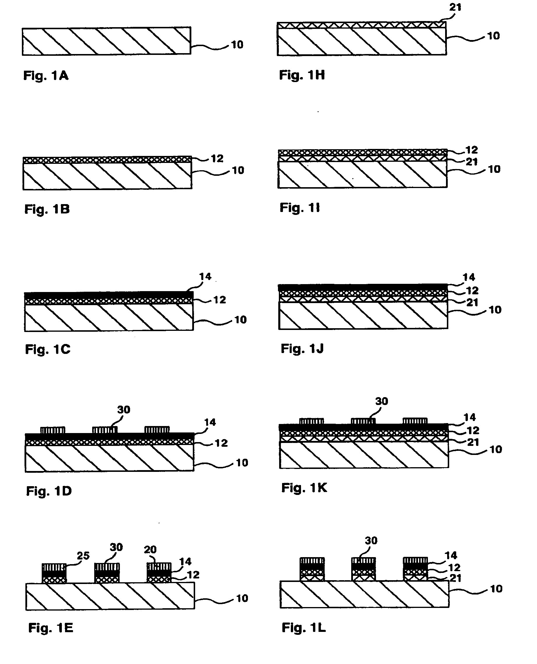
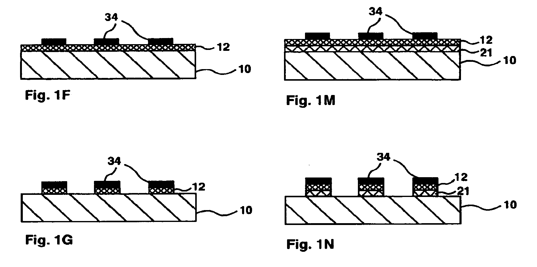
[0068]The following FIGS. 1A-27G are sequential, diagrammatic cross-sections illustrating the production of panels according to various embodiments of the invention. Each of the four basic methods has several variants. Each of these described method variants or method embodiments result in product embodiments which comprise a substantially imperforate light permeable material, a print pattern comprising a plurality of layers of marking material, one of the layers of marking material being a metallized layer and at least a part of the boundary of one of the layers of marking material being in substantially exact registration with a part of the boundary of another of the layers of marking material.

[0069]FIGS. 1A to 15L illustrate embodiments of the first method, which uses a solvent etch to remove layers of unwanted marking material from outside a resist layer.

[0070]FIG. 1A illustrates a light permeable material 10, typically a transparent material, which is coated with metallized lay...


PUM

PropertyMeasurementUnit
Thicknessaaaaaaaaaa
Thicknessaaaaaaaaaa
Thicknessaaaaaaaaaa

Abstract

A panel includes a light permeable material that is partially coated with superimposed layers and includes a metallized layer. A print pattern typically has a radiation-reflective surface facing one side of the panel and a radiation-absorbing surface facing the other side of the panel, for example to form a vision control panel, for example a one-way vision, see-through graphic panel.

Description

CROSS-REFERENCE TO RELATED APPLICATIONS[0001]This application claims the benefit of priority from U.S. Provisional Patent Application Ser. No. 60 / 776,932, titled “Partial Printing of a Substrate Using Metallization,” filed Feb. 28, 2006, the entire contents of which are incorporated by reference herein.BACKGROUND TO THE INVENTION[0002]1. Field of the Invention[0003]This invention relates to one-way and other vision control panels and methods of printing such panels.[0004]2. Description of Related Art[0005]One-way and other vision control panels are described in GB 2 118 096 and US RE 37,186, which reissued from U.S. Pat. No. 4,673,609. GB 2 118 096 discloses a transparent plastic substrate partially covered with a pattern of one color when viewed from one side, for example white, and another color when viewed from the other side, typically black.[0006]Depending partly upon conditions of illumination, through vision is typically totally or partially obscured from the white side, the ...

Claims


Application Information

Patent Timeline
IPC IPC(8): B32B3/10B44C1/22
CPCB44C3/005B44C5/0407Y10T428/24802B44F1/08B44F1/04
Inventor HILL, G. ROLANDVOSS, ANDREW JAMES
Owner CONTRA VISION
Why Eureka
Try Eureka