Gas turbine engine controls for minimizing combustion dynamics and emissions

a technology for gas turbine engines and controls, applied in the direction of process and machine control, hot gas positive displacement engine plants, machines/engines, etc., can solve the problems of mating hardware vibrating and moving relative to one, affecting the overall performance and durability of engine components, and causing significant wear and tear. , to achieve the effect of reducing combustion dynamics, creating combustion noise and vibration

Active Publication Date: 2009-09-03
ANSALDO ENERGIA SWITZERLAND AG
View PDF41 Cites 46 Cited by
  • Summary
  • Abstract
  • Description
  • Claims
  • Application Information

AI Technical Summary

Benefits of technology

[0008]By determining and controlling the fuel flow to the fuel circuits as a function of both a compressor inlet temperature and turbine reference temperature, combustion dynamics can be reduced. Extremely lean fuel conditions, which tend t

Problems solved by technology

There are a number of issues that affect the overall performance and durability of the engine components, especially the combustion section.
The combustion process creates varying pressure oscillations and dynamics in the combustion hardware that can result

Method used


Image

  • Gas turbine engine controls for minimizing combustion dynamics and emissions
  • Gas turbine engine controls for minimizing combustion dynamics and emissions
  • Gas turbine engine controls for minimizing combustion dynamics and emissions

Examples


Embodiment Construction

[0019]The subject matter of the present invention is described with specificity herein to meet statutory requirements. However, the description itself is not intended to limit the scope of this patent. Rather, the inventors have contemplated that the claimed subject matter might also be embodied in other ways, to include different steps or combinations of steps similar to the ones described in this document, in conjunction with other present or future technologies. Moreover, although the terms “step” and / or “block” may be used herein to connote different elements of methods employed, the terms should not be interpreted as implying any particular order among or between various steps herein disclosed unless and except when the order of individual steps is explicitly described.

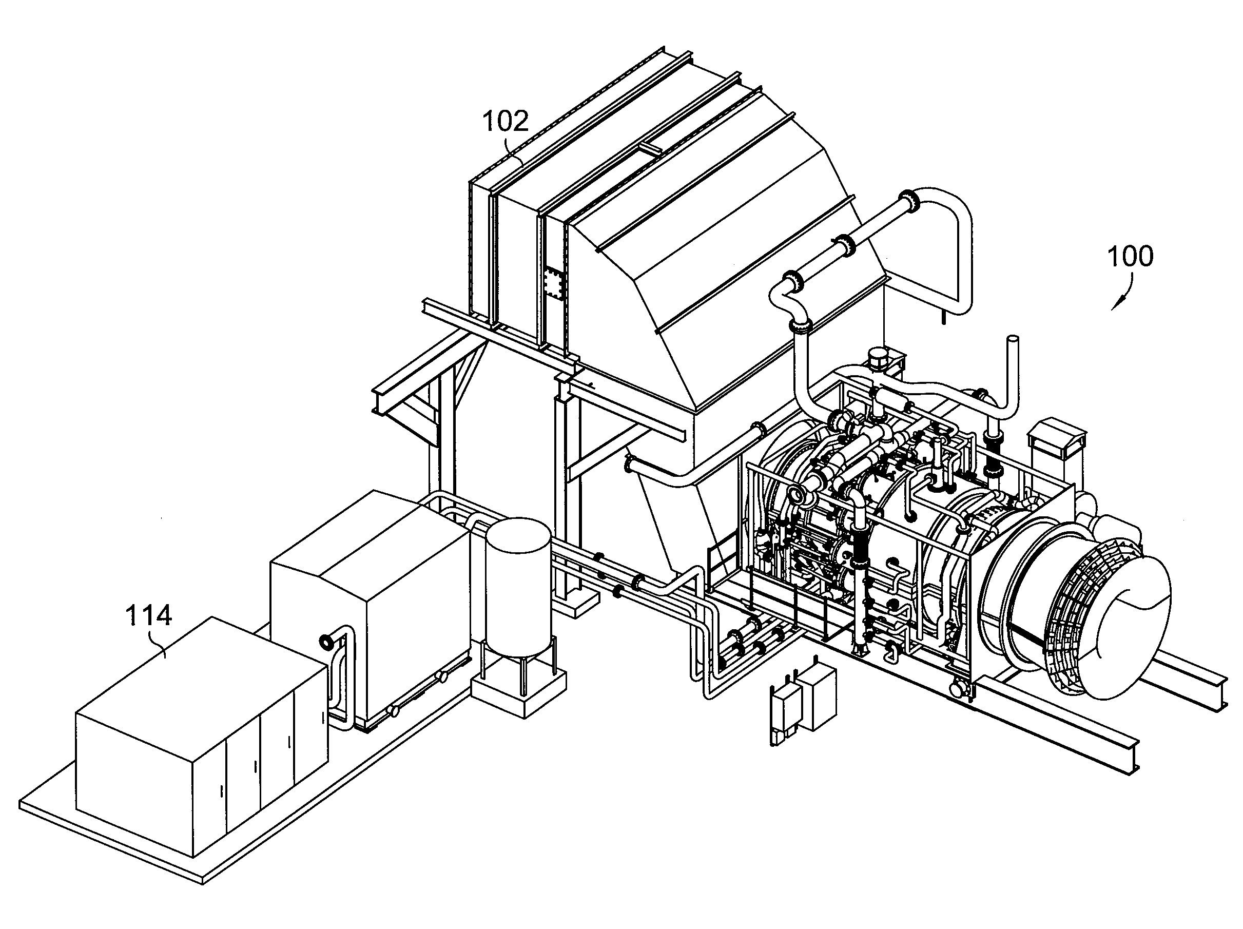
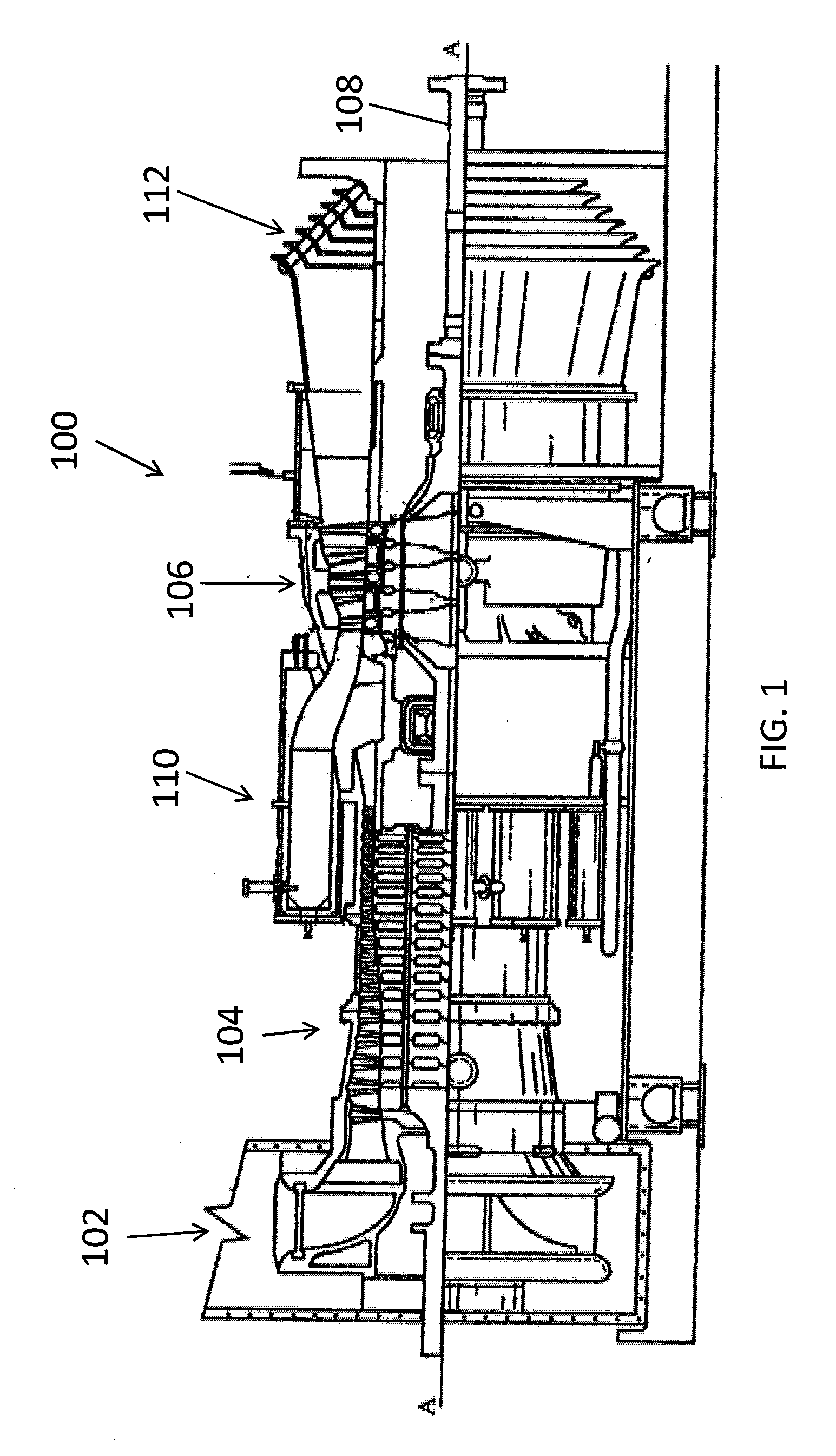
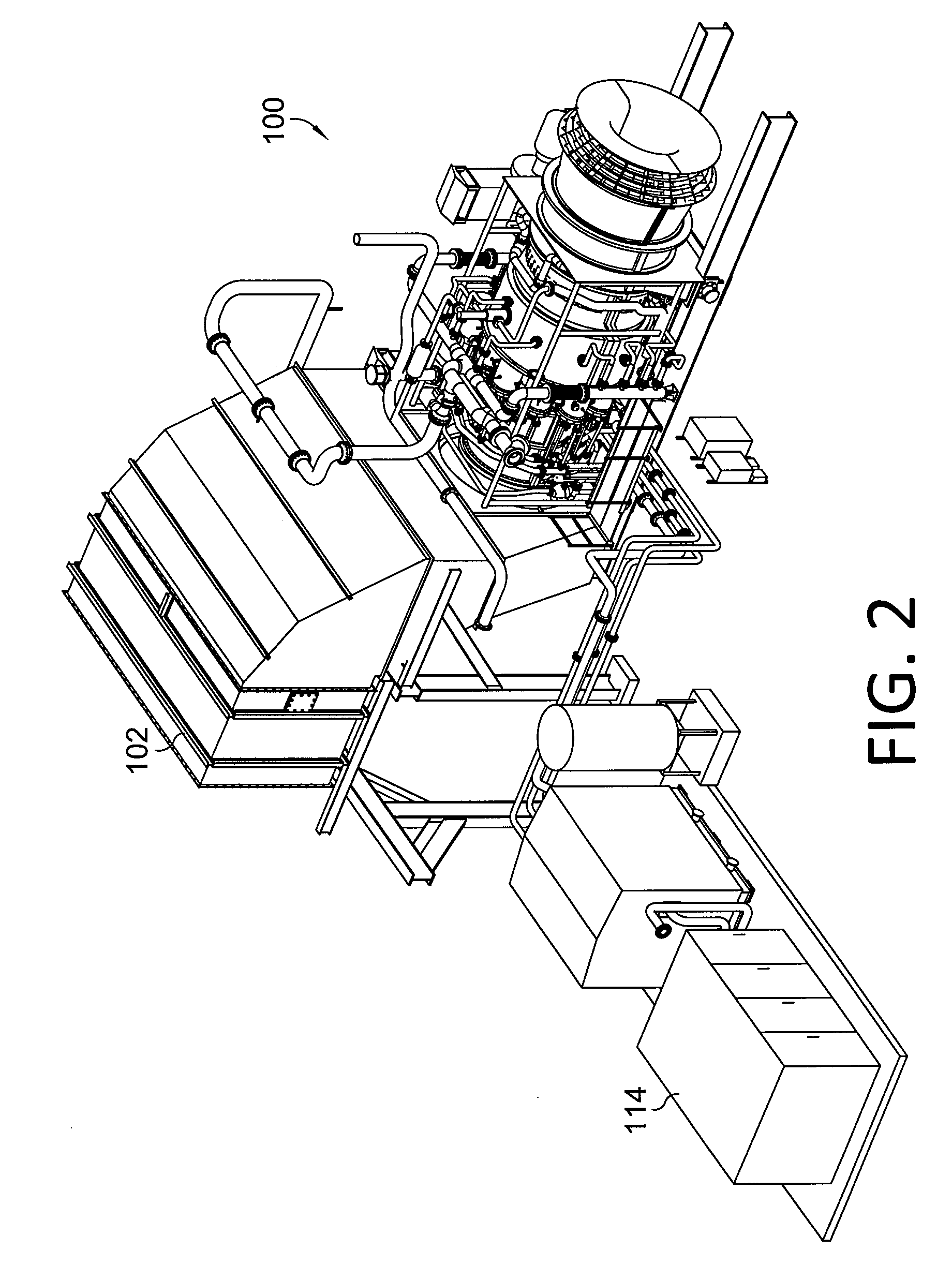
[0020]Referring initially to FIGS. 1 and 2, a gas turbine engine 100 for which the present invention is utilized is shown. The gas turbine engine 100 comprises an inlet 102, a compressor 104 that is coupled to a ...


PUM


Abstract

Embodiments for controlling a gas turbine engine to minimize combustion dynamics and emissions are disclosed. Methods and an apparatus are provided for controlling the gas turbine engine where a compressor inlet temperature is measured and a turbine reference temperature is calculated in real-time and utilized to determine the most-efficient fuel splits and operating conditions for each of the fuel circuits. The fuel flow for the fuel circuits are then adjusted according to the identified fuel split.

Description

TECHNICAL FIELD[0001]The present invention relates to gas turbine engines. More particularly, embodiments of the present invention relate to apparatus and method for reducing combustion dynamics and emissions.BACKGROUND OF THE INVENTION[0002]Gas turbine engines operate to produce mechanical work or thrust. Land-based gas turbine engines typically have a generator coupled thereto for the purposes of generating electricity. There are a number of issues that affect the overall performance and durability of the engine components, especially the combustion section. The combustion process creates varying pressure oscillations and dynamics in the combustion hardware that can result in significant wear. Specifically, the pressure oscillations can cause mating hardware to vibrate and move relative to one another. Excessive combustion dynamics can cause premature wear of mating hardware such that the hardware must be repaired or replaced.[0003]Typically, gas turbine combustors comprise multip...

Claims


Application Information

Patent Timeline
IPC IPC(8): F02C9/00
CPCF02C9/28F02C9/34F05D2270/303F23N2041/20F05D2270/708F05D2270/082F23N2241/20
Inventor MARTLING, VINCENT C.SO, PETERXIAO, ZHENHUARICKLIN, PLAZI
Owner ANSALDO ENERGIA SWITZERLAND AG
Why Eureka
Try Eureka