System, air valve assembly and method for air evacuation of plastic sealable storage bags

Inactive Publication Date: 2009-09-10
WIDGETEER
18 Cites 3 Cited by

AI-Extracted Technical Summary

Problems solved by technology

Other limitations of the related art will become apparent to those skilled ...

Benefits of technology

[0015]It is therefore an object of this invention to provide a system for converting virtually any sealable plastic or flexible paneled storage bag into a vacuum-sealed storage container for preserving the freshness of foods.
[0016]It is yet another object of this invention to provide a system for vacuum sealing foods ...

Abstract

A system, storage bag and method for evacuating air from a convention self-sealing storage bag. An air valve assembly includes inner and outer valve members, the inner valve member being positionable within the storage bag and having a tapered piercing spout adapted to pierce through a flexible panel. The outer valve member has a housing lockingly engagable over the piercing spout protruding outwardly through the panel. A perimeter edge of the housing is sealingly engagable against the bag panel and a mating groove formed into the inner valve member. The inner valve member is configured for temporary sealing engagement against the inner surface of the bag panel as air is removed from the interior of the storage bag out through the piercing spout and housing air outlets by a vacuum pump.

Application Domain

Check valvesPackaging by pressurising/gasifying +1

Technology Topic

EngineeringVacuum pump

Image

  • System, air valve assembly and method for air evacuation of plastic sealable storage bags
  • System, air valve assembly and method for air evacuation of plastic sealable storage bags
  • System, air valve assembly and method for air evacuation of plastic sealable storage bags

Examples

  • Experimental program(1)

Example

[0039]Exemplary embodiments are illustrated in reference figures of the drawings. It is intended that the embodiments and figures disclosed herein are to be considered to be illustrative rather than limiting.
DETAILED DESCRIPTION OF THE INVENTION
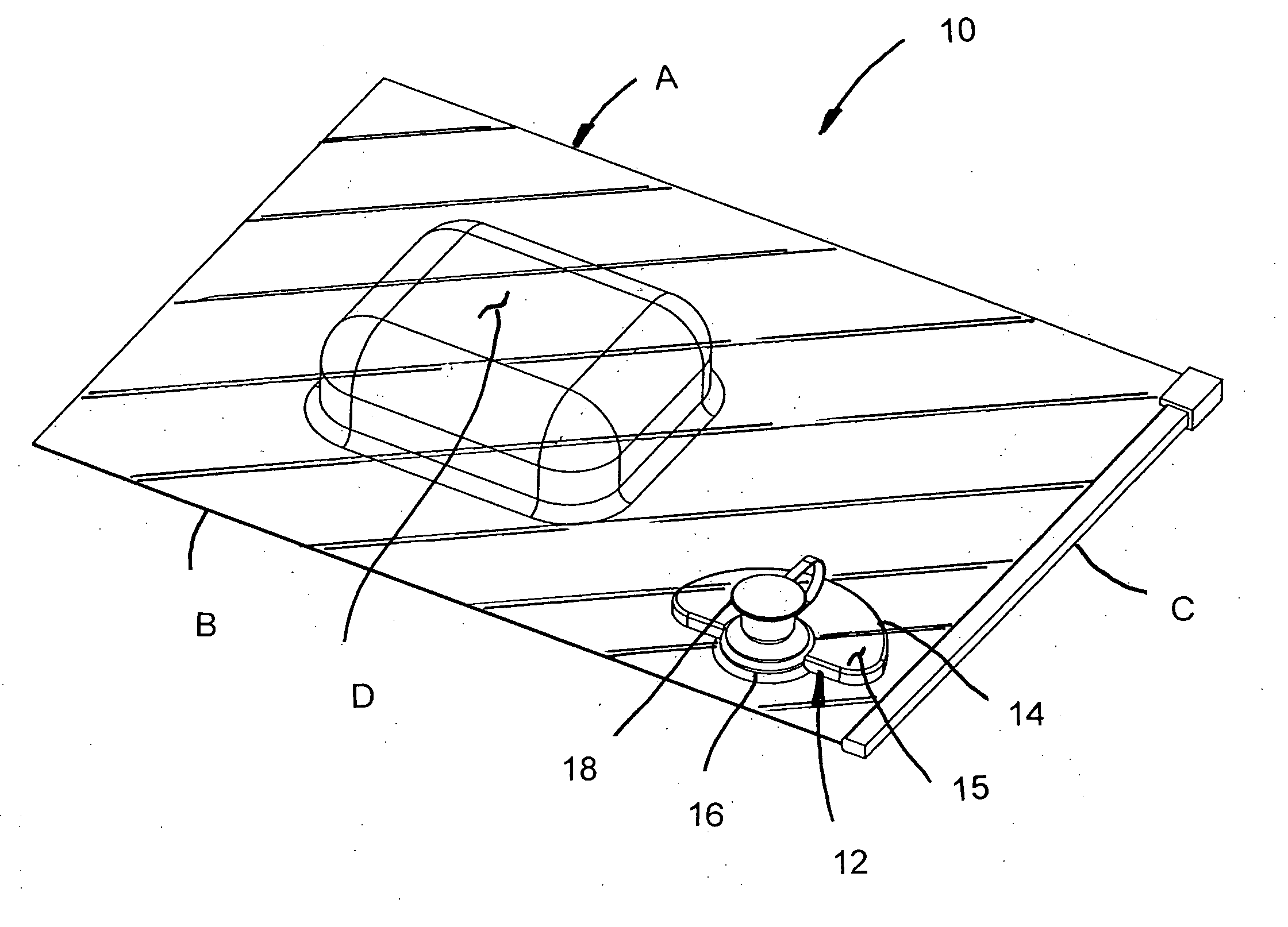
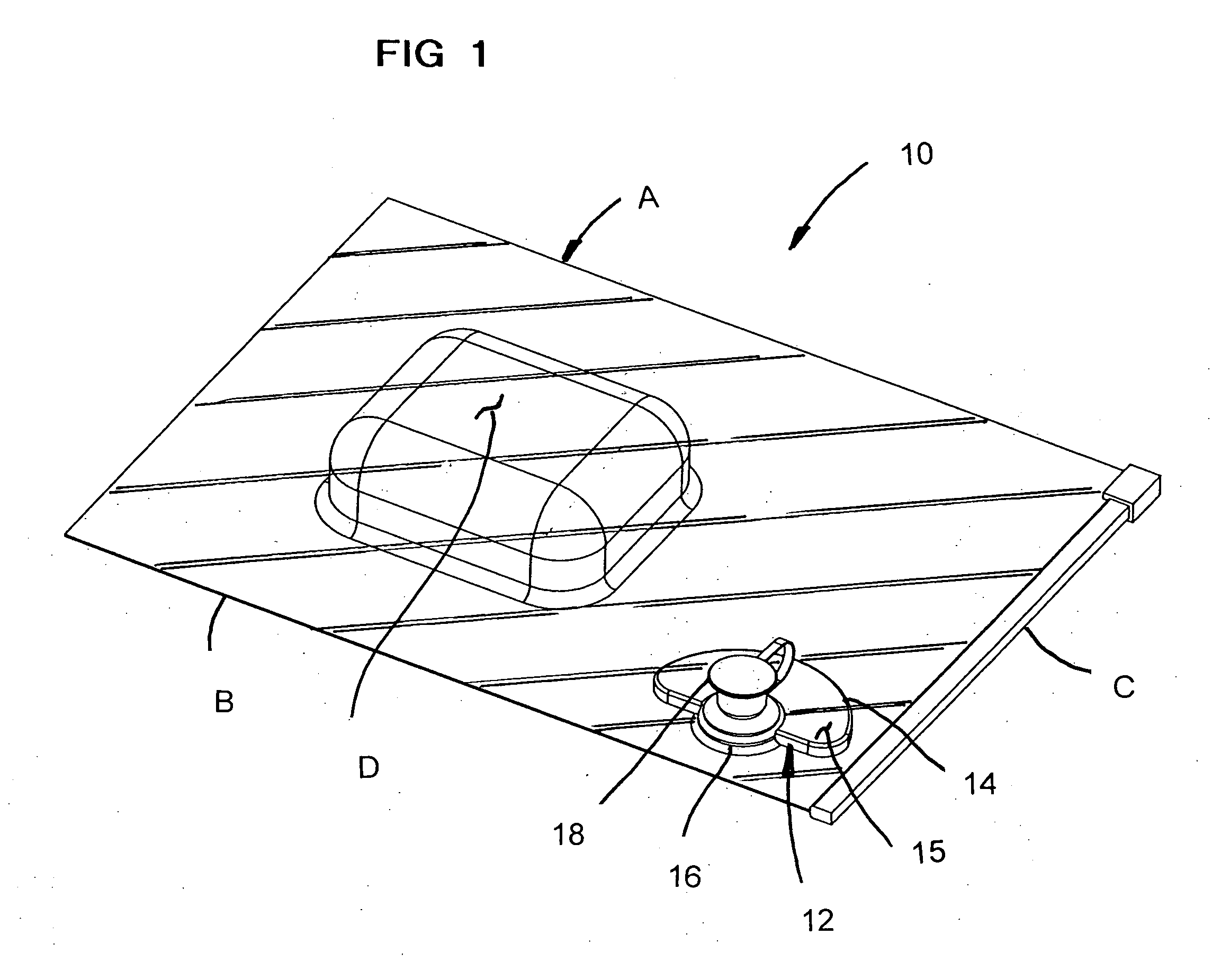
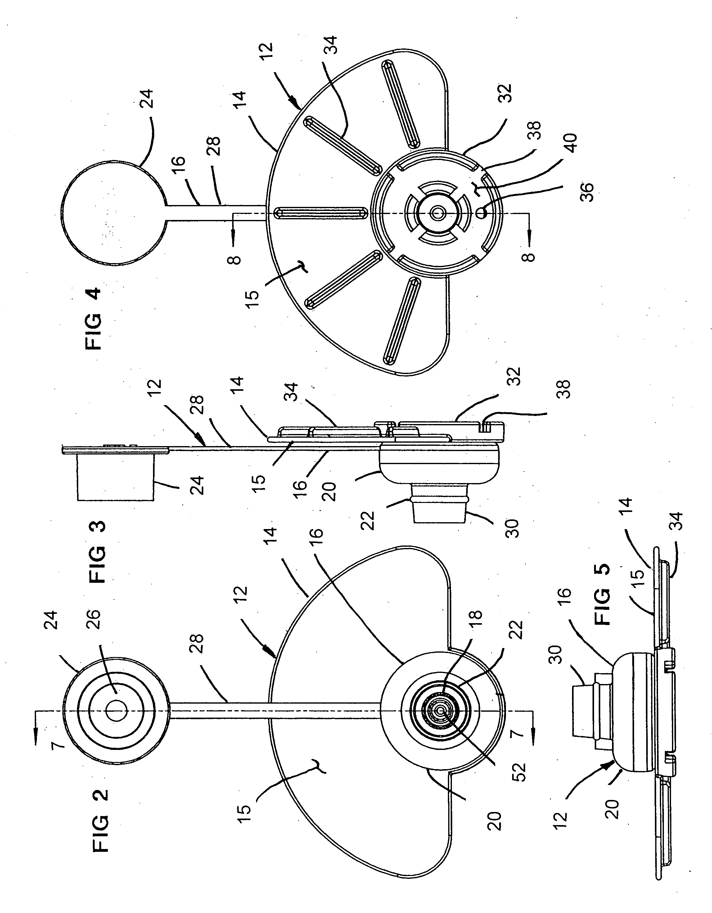
[0040]Referring now to the drawings, and firstly to FIGS. 1 to 8, the system of the invention in combination with a conventional plastic storage container or bag A is there shown generally at numeral 10. The system 10 includes an air valve assembly 12 which includes an inner valve member 14 and an outer valve member 16 installed into the conventional plastic storage bag or container A.
[0041]Initially, a food item or other storable goods D is placed within the open sealable end C of the bag A. Prior to this, the air valve assembly 12 was assembled onto one of the flexible side panels of the bag B as will be described in more detail in FIGS. 7 and 8. After installation of the air valve assembly 12 and insertion of the item D to be vacuum-sealed within the flexible storage bag A, the sealable end C is closed. Thereafter, a vacuum pump is utilized in conjunction with the air valve assembly 12 to evacuate substantially all air from within the sealed storage bag A, again as will be described in more detail herebelow.
[0042]The inner valve member 14 includes a molded plastic piercing spout 50 molded as a unit with a base 32 and further includes a stabilizing base plate 15 generally in the shape of a semi-circular flat disc extending outwardly from the plane of the base 32. As best seen in FIG. 8, after the inner valve member 14 is positioned within the flexible bag B, the piercing spout 50 is automatically positioned against an inner surface of one of the flexible bag panels E and is tapered so as to easily pierce through the panel E by manual pressure inwardly against and immediately around the piercing spout 50. By placing the other bag panel F of the bag B against a flat surface such as a table or kitchen counter, the base plate 15 may also be manually depressed or held to stabilize the inner valve member 14 within the bag B while this piercing process is accomplished.
[0043]The outer valve member 16, also formed of molded plastic material, includes a housing 20 having a tubular outlet 30 therefor in a concentric alignment with a continuous preferably planar sealing edge 42 and an outer air chamber 48. The housing 20 also includes a central longitudinal hole 53 which tightly engages around the cylindrical base 55 of piercing spout 50.
[0044]As the two valve members 14 and 16 are assembled together into the configuration best seen in FIGS. 7 and 8 with the inner valve member 14 within the storage bag B, a tight sealing engagement is accomplished between the central hole 53 and the spout base 55 which is secured by an annular bead 18 which snapingly engages into the enlarged bottom of the hollow interior 31 of spout air outlet 30. Cavities 54 enhance the inward resiliency of retaining bead 18 to facilitate installation and to resiliently enhance retentions between the inner and outer valve members 14 and 16.
[0045]The interactive dimensions between the height of housing 20 and that of retaining ring 18 are such that a substantial sealing pressure is exerted against the bag panel E between the sealing edge 42 and a sealing groove 44 formed around the piercing spout 50 to substantially trap that portion of the bag panel E therebetween. This arrangement establishes a sealed or closed airflow path from the interior of the storage bag B and the air outlet 30. To insure that air evacuation from the bag B is complete and unencumbered, spaces between the strengthening ribs 34 of the base plate 15 and air slots 38 between spacers or legs 46 prevent the other bag panel F from blocking the airflow path to an air evacuation port 36 formed through the base 32. Evacuation of air continues through the inner portion 48a of the hollow interior 48 of housing 20 into an air passage 56 for exhausting through an air outlet 52 formed centrally through the piercing spout 50.
[0046]Importantly, as air is evacuated from the bag B as above described, the thin sheet flexible plastic material forming the bag B and panels E collapses inwardly from the position shown in phantom at G surrounding the base 53 of the piercing spout 50 to the position shown in phantom at H. In doing so, this portion of the panel E contacts against ridge 58 formed continuously around the spout base 55 to effect a vacuum seal therebetween. When substantially all of the air has been removed from the bag B, the greatest amount of sealing occurs at this point 58 for a time sufficient for the vacuum pump to be removed from air outlet 30 as described herebelow and for sealing cap 24, held in spaced relation by tether 28 from housing 20, to be flexed over upon itself and engaged over the air outlet 30. The distal end of the air outlet 30 presses against the sealing ring 26 to effect permanent vacuum sealing of the interior of the bag B, the cap 24 being held in this position by mating retaining bead 22 within retaining groove 25.
[0047]Referring now to FIGS. 9 to 16, the preferred embodiment of the air evacuation pump of the system 10 is there shown generally at numeral 60 and includes a molded plastic pump body 62 having finger-engaging handle 64 extending laterally therefrom for activation of the pump 60. A soft resilient elastomeric valve seat 66 held in place by mating retaining beads 68 within a retaining groove 70 formed within the pump body 62. The valve seat 66 includes a tapered cavity 92 which matably engages over the outer surface of the air outlet 30 of the outer valve member 16 previously described. This establishes a temporary positive seal therebetween for air evacuation from the bag B as previously described.
[0048]An elongated pump actuator 74 is slidably engagable within the inner bore of the pump body 62. This relationship is made sealable by a flexible actuator seal 90 which sealingly and biasingly engages against the inner bore of the pump body 62. An actuator stem 80 is snapably engagable over the distal end of pump actuator 74 by the resilient interengagement between the inwardly extending retaining tabs 94 best seen in FIGS. 13 and 16 into a retaining groove 78. Note that there is an air clearance or passageway 102 between the inner surface of the actuator stem 80 and the outer surface of the distal end portion of the pump actuator 74 for the release or discharge of air in the direction of arrow M described more completely herebelow.
[0049]The pump assembly 60 also includes an elongated return spring 72 positioned at one end within a spring seat 88 formed concentrically into the proximal end of valve seat 66 while the other end of the return spring 72 is positioned within an elongated spring cavity 84 of pump actuator 74.
[0050]The actuator stem 80 also includes a longitudinally extending stem 82 fitted in spaced relationship within an elongated stem well 104 of the pump actuator 74. A sealing or check ball 76 is floatingly positioned to sealingly engage within a sealing ball seat 98 formed at the proximal end of the stem weld 104. When the sealing ball 76 is in the position shown in FIG. 15, the sealing ball seat 98 is sealed. When the pump actuator 74 is depressed inwardly in the direction of arrow K, the sealing ball 76 disengages from sealing engagement with sealing ball seat 98 and air within the pump body 62 is discharged therefrom through air passage 100 and outwardly in the direction of arrow M through the air discharge passage 102. Note that the distal end of stem 80 is closely spaced at 86 with respect to sealing ball 76. When pressure against the distal end of the actuator stem 80 is released, the return spring 72 forces the pump actuator 74 outwardly in the direction of arrow L and air from within the sealed storage bag A is drawn in the direction of arrow A through air conduit 96 of valve seat 66 to effect air evacuation from the sealed storage bag B.
[0051]Referring now to FIGS. 17 to 19, another embodiment of the outer valve member 16′ is there shown in conjunction with the addition of a ring-shaped sealing ring 106 which is formed of resilient elastomeric material, preferably SANTOPRENE or SARLINK, 40 shore “A” derometer. In some situations, the thin flexible plastic material forming the panels E collapses inwardly as described with respect to FIG. 8 hereinabove, but does not effect a sufficient vacuum seal against the sealing ridge 58 in FIG. 8 as there described to allow the spout to be capped or otherwise sealed.
[0052]To insure an adequate continuing seal within the vacuum bag B until the spout is sealed, the sealing ring 106 is fitted into the hollow interior of the housing 20′ which has slight accommodating interior modifications to receive the sealing ring 106 as shown in FIG. 19. The flexible sealing flange 110 contacts against the sealing ridge 116 of the base 32 and resiliently flexes to overcome the interference shown. This additional pressure against both sides of the flexible panel E enhances the temporary vacuum sealability. To further enhance the biased resiliency of the sealing ridge 114, a collapsible cavity 112, extending radially outwardly from the central air passage 108, resiliently collapses slightly during the assembly of the outer valve housing 20′ onto the base of the spout as previously described.
[0053]While a number of exemplary aspects and embodiments have been discussed above, those of skill in the art will recognize certain modifications, permeations and additions and subcombinations thereof. It is therefore intended that the following appended claims and claims hereinafter introduced are interpreted to include all such modifications, permeations, additions and subcombinations that are within their true spirit and scope.

PUM

no PUM

Description & Claims & Application Information

We can also present the details of the Description, Claims and Application information to help users get a comprehensive understanding of the technical details of the patent, such as background art, summary of invention, brief description of drawings, description of embodiments, and other original content. On the other hand, users can also determine the specific scope of protection of the technology through the list of claims; as well as understand the changes in the life cycle of the technology with the presentation of the patent timeline. Login to view more.

Similar technology patents

Lightweight Inflation Device

InactiveUS20200248700A1easily portablequick and easy
Owner:CAMP TEK

Electronic signaling device

ActiveUS10997830B1promote efficiencyeasily portable
Owner:THAYER DAVID B

Refresh deodorizing strips

InactiveUS20120251601A1easily portablesmall package
Owner:MALIK PALAVI

Name card cartridge

InactiveUS20060070275A1easily portableconveniently check
Owner:LIU TIEN LUN

Portable head support

ActiveUS20180070749A1easily portable
Owner:HELD JOAN MARY
Why Eureka
Try Eureka