Mass Velocity and Area Weighted Averaging Fluid Compositions Sampler and Mass Flow Meter

Active Publication Date: 2009-09-10
LOS ROBLES ADVERTISING
View PDF4 Cites 11 Cited by
  • Summary
  • Abstract
  • Description
  • Claims
  • Application Information

AI Technical Summary

Problems solved by technology

The problem of obtaining real-time accurate measurements of aerosol and gas in processes in conduits with u

Method used


Image

  • Mass Velocity and Area Weighted Averaging Fluid Compositions Sampler and Mass Flow Meter
  • Mass Velocity and Area Weighted Averaging Fluid Compositions Sampler and Mass Flow Meter
  • Mass Velocity and Area Weighted Averaging Fluid Compositions Sampler and Mass Flow Meter

Examples


Embodiment Construction

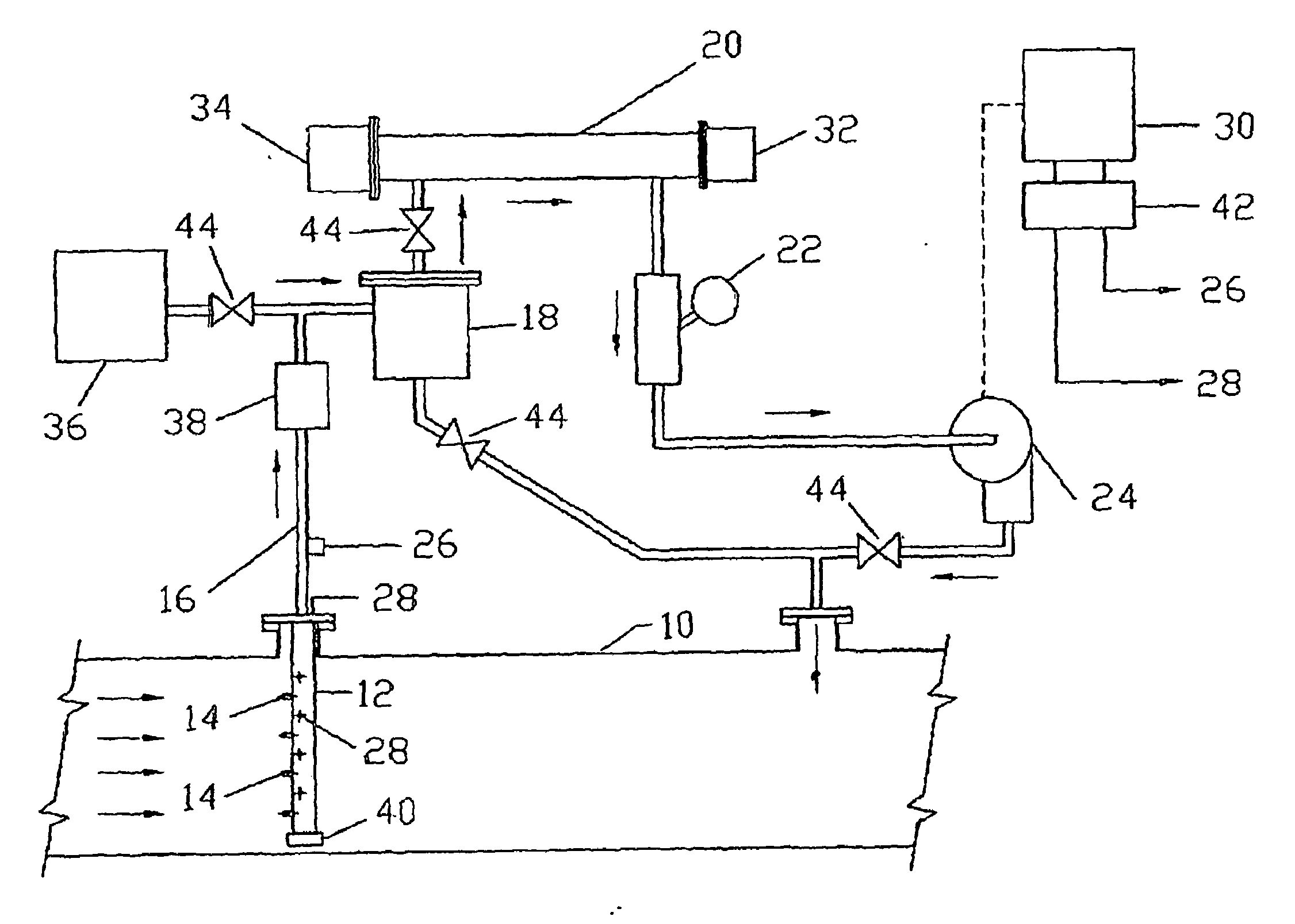
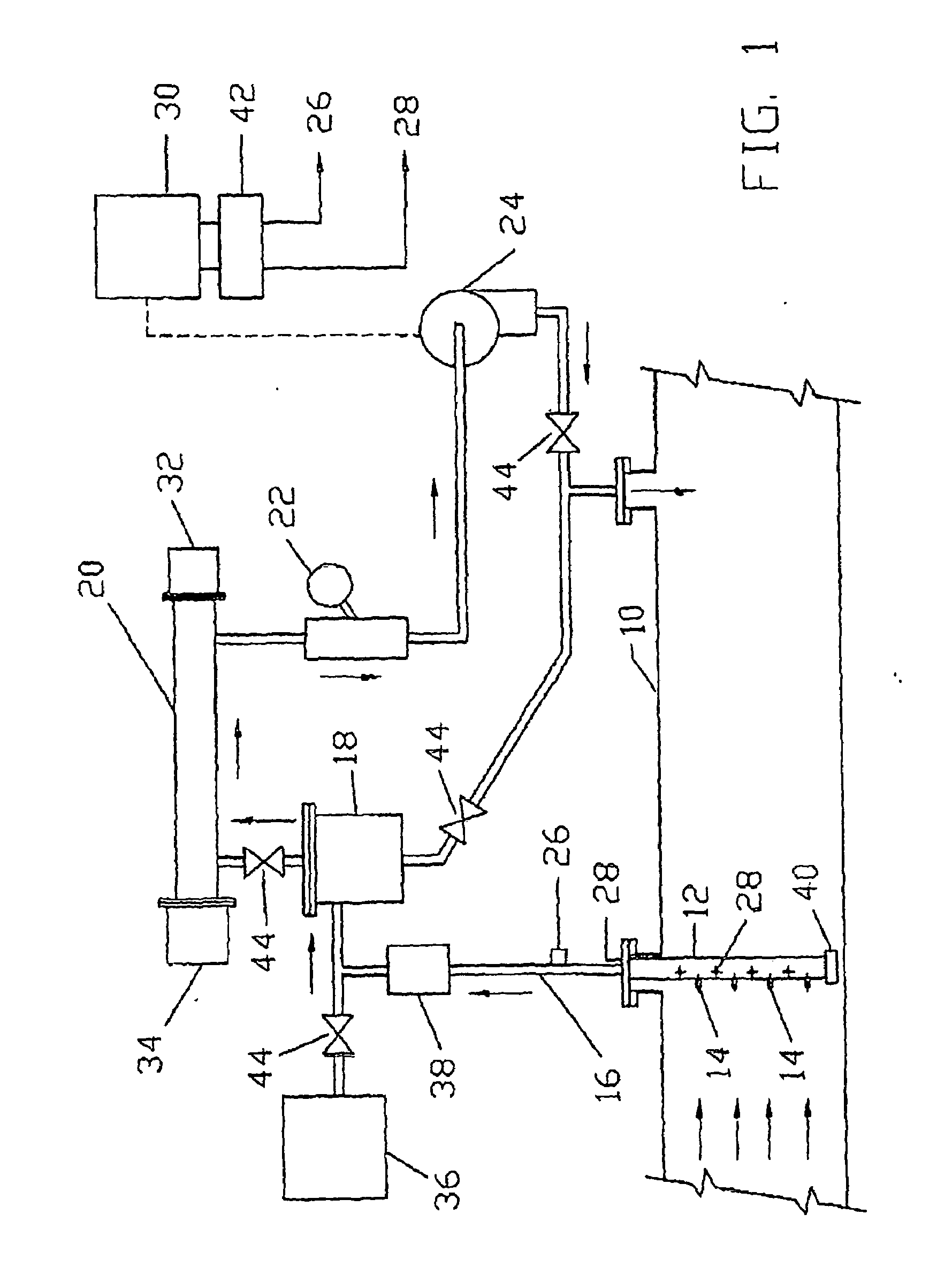
[0073]A diagram showing the system of the present invention is shown in FIG. 1. The present invention is a mass-velocity weighted sampling probe and is used to obtain truly representative samples for the analyzers. The present invention pneumatically performs the mass-velocity and area averaging according to the following equation which is the correct definition of the True Concentration Average.

Ci_=∫∫ρ(x,y)V(x,y)C(x,y)ixy∫∫ρ(x,y)V(x,y)xy

Where:

[0074]Ci is the mass-velocity and area average concentration in the conduit of fluid component i, ρ(x, y) is the fluid density, V(x, y) is the fluid velocity and C(x, y), is the concentration of Component i.

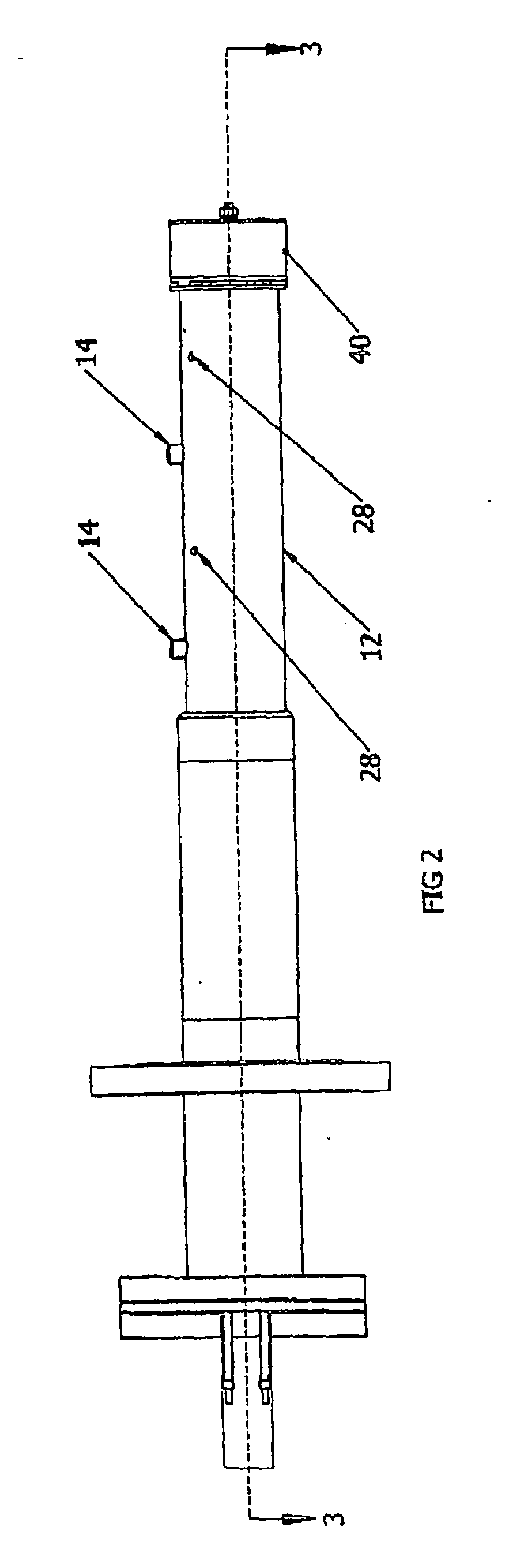
[0075]As shown in FIG. 1, a probe 12 is installed which extends perpendicularly into the conduit, vent, duct or stack 10 in which the measurements are to be taken. Preferably, a plurality of probes 12 are used to effectively sample over the area of the conduit. Each probe 12 is located at the centroid of equal flow area locations within the...


PUM


Abstract

A sampling device and method for use with a conduit for fluid which has at least one sampling nozzle or sample hole. The sample collected is directed to a manifold where an analysis is conducted and flow rates are measured. The sampled fluid is returned to the conduit. The Static Pressure Control System uses a vacuum pump or other device to equalize the static pressures of the sample nozzle collection manifold and the Static Pressure of the Conduit to achieve the mass-velocity and area-weighted average fluid composition and mass flow rate.

Description

BACKGROUND OF THE INVENTION[0001]1. Field of the Invention[0002]The present invention is a sampling method and a device for obtaining real time, accurate measurements of the fluid composition and mass flow rates in conduits having uniform or non-uniform fluid composition, velocity and temperature profiles. The present invention includes the sampling of all fluids, including gases, aerosols, particulates, liquids and combinations of the same.[0003]2. Description of Related Art[0004]The problem of obtaining real-time accurate measurements of aerosol and gas in processes in conduits with uniform or non-uniform gas velocity, composition, temperature profiles, swirl and turbulence is a common one. Simply inserting a single-point gas sampling probe into a conduit of unknown characteristics only samples the fluid composition in one location which is not representative of the entire flow field in the conduit. The largest error is generally due to the velocity which can easily vary by a fact...

Claims


Application Information

Patent Timeline
IPC IPC(8): G01F1/76G01N1/22
CPCG01F1/46G01F1/6842G01N1/2035G01N1/16G01F5/00
Inventor KURZ, JEROME L.
Owner LOS ROBLES ADVERTISING
Why Eureka
Try Eureka