Vehicle disk brake

Active Publication Date: 2009-09-10
HL MANDO CORP
View PDF6 Cites 0 Cited by
  • Summary
  • Abstract
  • Description
  • Claims
  • Application Information

AI Technical Summary

Benefits of technology

[0012]In addition, the manual release part includes a stem part formed therein with a fixing groove through which the manual release part is fixed to the pad

Problems solved by technology

However, in the conventional vehicle disk brake, if the disk and the friction pads are locked while making contact with each

Method used


Image

  • Vehicle disk brake
  • Vehicle disk brake
  • Vehicle disk brake

Examples


Embodiment Construction

[0022]Reference will now be made in detail to the embodiments of the present invention, examples of which are illustrated in the accompanying drawings, wherein like reference numerals refer to the like elements throughout. The embodiments are described below to explain the present invention by referring to the figures.

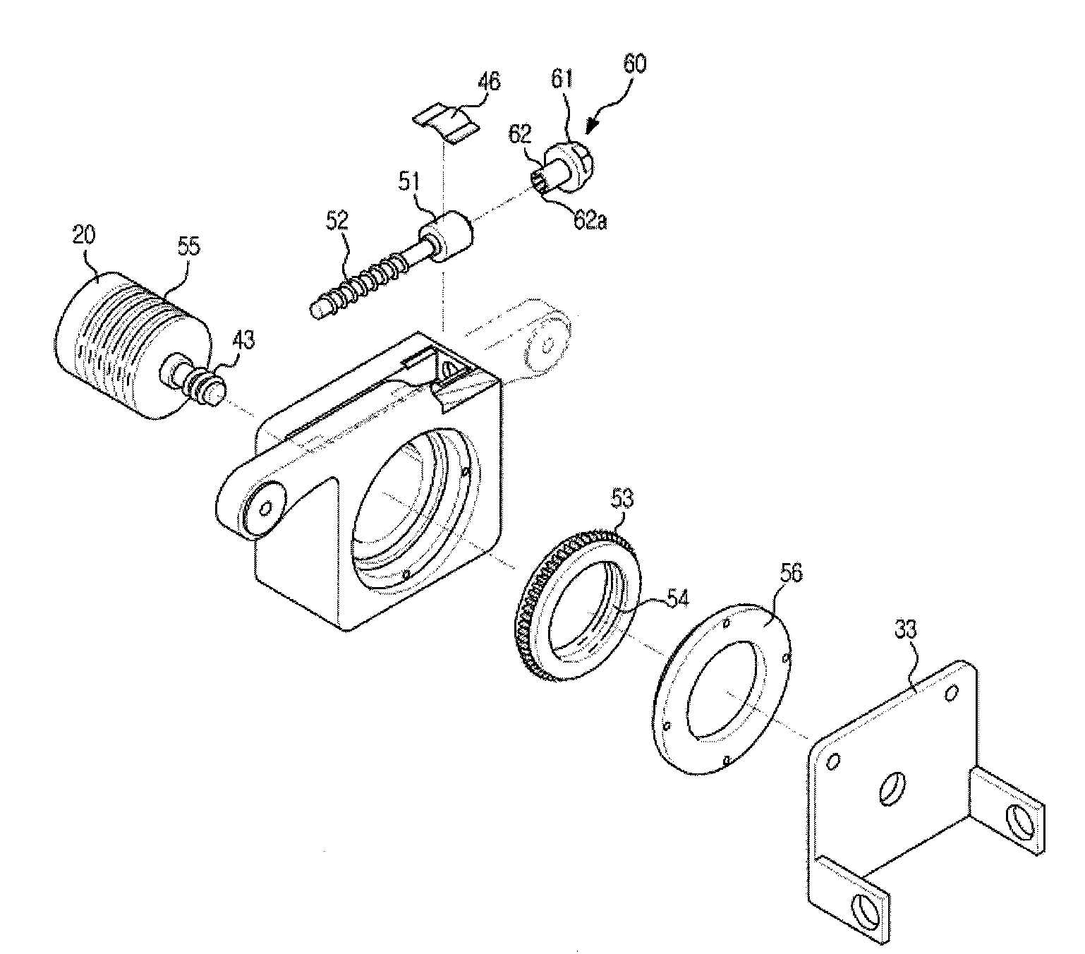
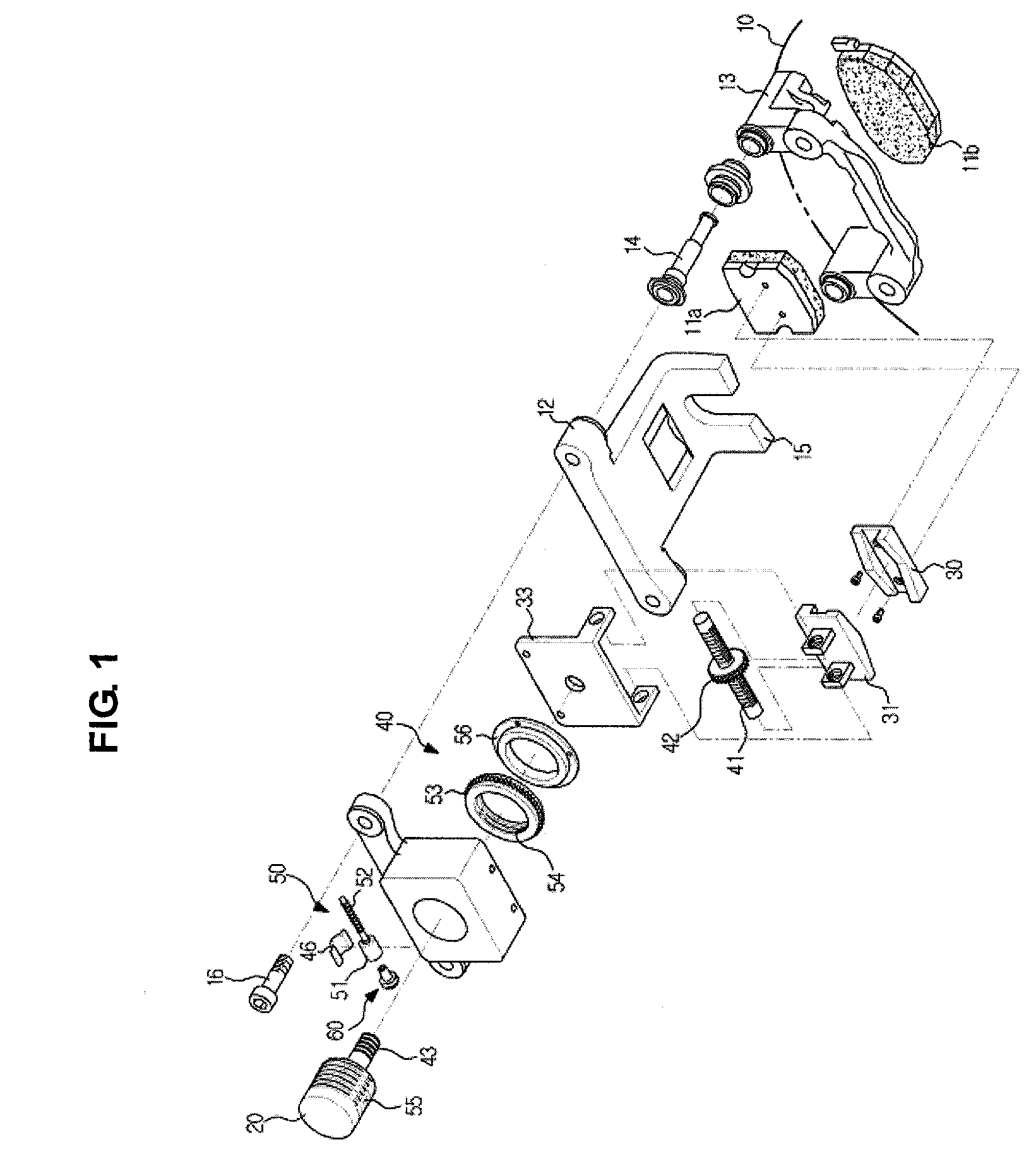
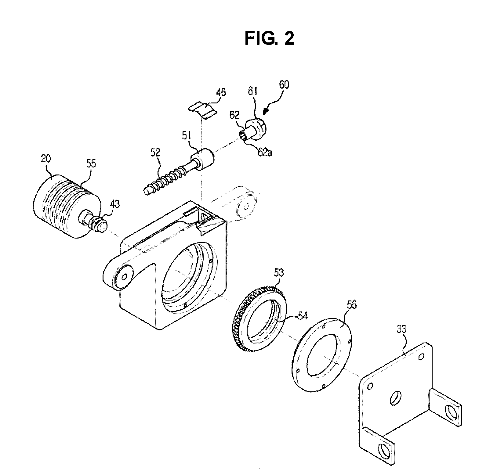
[0023]As shown in drawings, a disk brake for a vehicle according to the present invention is used to obtain braking force by allowing friction pads 11a and 11b to make contact with both sides of a disk 10, which has a disk shape and rotates together with a wheel (not shown) of the vehicle, respectively.

[0024]The disk brake includes a caliper housing 12, which has the pair of friction pads 11a and 11b attached to both inner sides of the caliper housing 12 in opposition to each other, and a carrier 13, which is fixed to the vehicle to allow the caliper housing 12 to move back and forth.

[0025]In order to allow the caliper housing 12 to move back and forth with respect to ...


PUM


Abstract

Disclosed is a disk brake for a vehicle having a manual release unit, capable of manually releasing the contact of a disk and a friction pad which are locked in a braking state. The disk brake includes a disk rotating together with a wheel of the vehicle, a friction pad which makes contact with a side surface of the disk to generate braking force, a wedge member to which the friction pad is attached, a drive motor which generates driving force to move the wedge member in a direction of the disk, a power transmission part which sifts rotational motion of the drive motor into a linear motion of the wedge member, a pad compensation part which maintains a uniform gap between the friction pad and the disk, and a manual release part installed in the pad compensation part such that contact between the friction pad and the disk is manually released when the friction pad and the disk are locked in a braking state due to friction between the friction pad and the disk.

Description

CROSS-REFERENCE TO RELATED APPLICATIONS[0001]This application claims the benefit of Korean Patent Application No. 10-2008-0021359, filed on Mar. 07, 2008, in the Korean Intellectual Property Office, the disclosure of which is incorporated herein by reference.BACKGROUND OF THE INVENTION[0002]1. Field of the invention[0003]The present invention relates to a vehicle disk brake. More particularly, the present invention relates to a vehicle disk brake provided with a manual release unit capable of manually releasing contact between a disk and a friction pad, which are locked in a braking state of the vehicle.[0004]2. Description of the Prior Art[0005]In general, a vehicle disk brake produces braking force by partially pressing a disk from both sides of the disk that rotates together with a wheel, by using friction pads. Such a vehicle disk brake comprises a disk rotating together with a wheel of the vehicle, friction pads that generate braking force through contact with one side of the d...

Claims


Application Information

Patent Timeline
IPC IPC(8): F16D65/14F16D65/18
CPCB60T13/741F16D65/567F16D2065/386F16D2127/10F16D2125/40F16D2125/52F16D2127/04F16D2121/24F16D65/095F16D65/04
Inventor KIM, JOO GON
Owner HL MANDO CORP
Why Eureka
Try Eureka